
Owner's manual

5
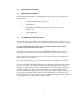
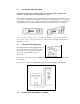
Insert the water tubes from the probe into WATER INLET and OUTLET connectors on the
front panel of the controller. These tubes are interchangeable -- direction of flow is not
important.
Insert polarized electrical connector from stage into POWER OUTPUT socket on front of
the controller. Twist the locking nut in a clockwise direction to lock connector to the
controller.
Insert blue thermocouple connector into socket labelled SENSOR B - STAGE.
Switch SENSOR INPUT to B position.
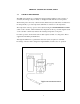
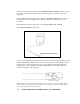
To protect the tip during shipment and when not in use, a clear protective sheath is provided
with the Thermal Probe. The protective sleeve has a bayonet-type, locking feature and can
be left in place on the probe shaft. To expose the tip, simply twist the sheath until the
retaining screw is in the radial slot and slide the sheath back or forward along the probe
shaft. Twist it again to lock it in place.
Warning: The probe is robust when handled and stored properly. Care should be taken to
ensure that it is not dropped on a hard surface or otherwise severely jarred. It should be
stored in the packing box when not in use.
2.6 CONNECTION TO AC POWER SUPPLY AND SWITCH ON