
Operating Instructions and Installation Instructions
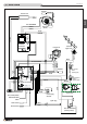

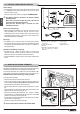


Solution 1 - Fig. 29 - 30:
The stove is installed in the room which is to be heated, with the hot
air directed to the front only, as when the stove arrives from the factory
(Fig. 29). Alternatively the air can ow to the rear by connecting a 3” / 75
mm-diameter exible pipe to the fan outlet (Fig. 30). In this set-up the
stove heats the room where it is installed by radiation only, and heats
the adjoining room through the ductwork to the rear.
a For the example shown in g. 30 it is necessary to use an
outlet vent which is permanently open.
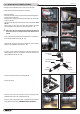
Solution 2 - Fig. 31:
The stove is installed in the room to be heated with the hot air ducted
to the front and, with the installation of a Y-element, also to the rear
thereby allowing the heating of a second room. A Ø 3” / (Ø 75 mm)
exible pipe with a maximum length of 30’ / (9 m) is connected to the
fan outlet (Fig. 31).
a For the example shown in g. 31 it is necessary to use an
outlet vent which is permanently open.
Solution 3 - Fig. 32:
Extension of the previous solution, with the stove installed in the room
to be heated and the air ow ducted to the front and the rear, but using
a second Y-element to double the ducting at the rear as shown.
Maximum total length of the exible pipe 30’ / (9 m). (Fig. 32).
a For the example shown in g. 32, for efcient ducting and to
avoid overheating, the outlet vent closest to the Y-element
must be partially open but never closed to avoid overheating.
4’ / (1 m)
Non-closable
vents
Non-closable vent
30’ / (9 m)
20’ / (6 m)
5’ / (1.5 m)
Partially
open vent
Fig. 29
Fig. 30
Fig. 31
Fig. 32
DT2030164-00
DT2030165-00
DT2034677-00
DT2030167-00
H07031310 / DT2002112 – 00
24
English