
Operating Instructions and Installation Instructions
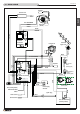

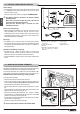


Wall and oor ducting - Fig. 33 / 36
For efcient ducted heat distribution:
- lag the exible pipe with a 0.79” / (2 cm) thick insulation (e.g. mineral
bre, ceramic bre, rock bre) to limit heat loss and to guarantee a
sufciently warm air temperature;
- the insulation must have a specic weight equal to or more than 50
kg/m³ with working temperature limit of at least 482°F / (250°C).
Thermal conductivity λ (100°C) ≤ 0,050 W/mK.
- Material with code “AGI Q132” or “DIN 18895” is allowed for thermal
insulation;
- the maximum total length of the exible pipe connected to the fan
must not exceed 32.8’ / (10 m).
a If the insulating material is not enclosed under the oor or
within the walls, it must be xed to the surface with suitable
fastenings at intervals of 11.8” / (30 cm).
A few examples of how the exible pipe can be installed in walls or
oors are given to the side.
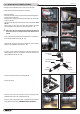
Safety ducting distance - Fig. 37
When hot air is to be ducted using a Ø 3” / (Ø 75 mm) exible pipe to
adjoning rooms the minimum lenght shall not be under 4” / (10 cm)
which corrisponds to the minimum distance allowed from the wall to
rear of the stove.
If the exible pipes go throught combustible walls and ceilings the
minimum required clearance is 1/2” / (1,3 cm).
Such space if made by air is allowed but it is reccomended to ll this
space with insulation (e.g. mineral bre, ceramic bre, rock bre)
wrapped around the exible pipe.
a The exible pipes are hot while in operation. If they aren’t
insulated and pass through a room (typically in the space
behind the stove) keep children, clothing and furniture away.
Contact may cause skin burns.
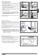
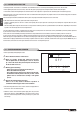
Hot air outlet vent radiation area - Fig. 38
A safety area must be ensured around the hot air outlet vent within
which there must be no ammable objects (furniture, carpets, curtains,
etc.) or heat sensitive materials (wood, plastic, etc.).
The diagram to the side shows the measurements for this safety area,
which includes 23.6” / (600 mm) from the upper edge of the vent.
a If the oor is ammable, the hot air outlet vents must be
located at least 7.9” / (200 mm) from the oor.
4"
(102 mm)
1/2"
(13 mm)
1/2"
(13 mm)
FLEXIBLE
PIPE
COMBUSTIBLE
WALL
MINIMUM REQUIRED
CLEARANCE
MINIMUM LENGHT
R 23.6” / (60 cm)
23.6” / (60 cm)
23.6” / (60 cm)23.6” / (60 cm)
HOT AIR OUTLET VENT
Fig. 33 Fig. 34
Fig. 35 Fig. 36
Fig. 37
Fig. 38
H07031310 / DT2002112 – 00
25
English
DT2030168-00
DT2030170-00
DT2030169-00
DT2030171-00
DT2033375-00
DT2030172-00