
Operating Instructions and Installation Instructions

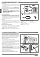


Power cable (6)
• The stove/rebox comes with a power cable which must be connected
to a 230V/50Hz mains socket. Connection to the rear of the stove/
rebox is shown in g. 39.
• The power rating is indicated in the paragraph “TECHNICAL DATA”.
a The appliance must be connected to an efcient earthing/
grounding system.
Ensure that in its normal position the power cable does not
come into contact with any heated parts.
Ensure that the electrical plug is accessible also after
installation of the stove.
Room sensor connection (5)
• When installing the stove/rebox, it is necessary to connect the room
sensor (provided) to the correct jack (Fig. 39). The sensor can be
positioned as shown in g. 39, otherwise remove the band, uncoil the
lead and then place the sensor in a spot where a more accurate room
temperature reading can be obtained.
Pipe tap (3)
• The appliance has an external socket for measuring the pressure
(vacuum) of the ue gas outlet pipe. This control and verication should
be carried out by authorised personnel at the time of installation or
during maintenance.
Connection to the DB9 serial socket (7)
• The appliance has a DB9 serial socket, which is used to check
appliance operation. Controls should be carried out by authorised
personnel at the time of installation or during maintenance.
• The optional GPRS kit, if ordered, may be connected to the DB9 serial
socket.
DT2011891-00
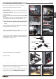
5.2 ELECTRICAL CONNECTIONS AND CONTROLS
DT2030078-01
The appliance is designed to be connected to an external room thermostat
with normally closed contact (not supplied by the manufacturer).
To connect the thermostat use a 2x0.5 mm
2
cable secured with a PG7
cable gland to be inserted in the relative hole in the rear panel (Fig. 39).
Only authorised personnel should carry out this operation.
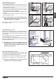
To install, proceed as follows:
- Disconnect the stove from the electrical power line.
- Access to the electronic board. It could be necessary to remove part
of the cladding (see INSTALLING /REMOVING THE CLADDING) and the
protective panel of the electronic board (if present).
- Remove the knockout to be found in the rear panel (position 4 – gure
39).
- Clamp the thermostat cable with the PG7 cable gland and insert the
gland into the hole in the rear panel (Fig. 42).
- Connect the thermostat cable terminal (C. - N.C. common - normally
closed contact) to a 2 PIN terminal and then insert this in the NH2O
position on the board as shown in gure 40.
- Pay attention to the wiring trail inside the stove which must not make
contact with hot or moving parts.
- Ret all the components previously removed.
a Do not connect any live element to the terminal, NH2O.
DT2010997-02
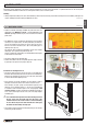
5.3 INSTALLING THE EXTERNAL THERMOSTAT
NH2O
1
2
3
4
1 Thermostat
2 Electronic board 2-pin terminal
3 Cable gland PG 7
4 Thermostat cable terminal
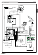
1
5
6
3
4
7
2
1 External jack for connection of
room sensor
2 Socket for power lead
3 Pipe tap
4 Knockout for inserting cable gland
PG7 for connection of external
thermostat
5 Room sensor
6 Power cable
7 DB9 serial socket
Fig. 39
Fig. 40
Fig. 41
Fig. 42
H07031310 / DT2002112 – 00
26
English
DT2034323-00
DT2030076-00