
Operating Instructions and Installation Instructions


DT2012027-00
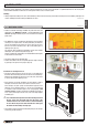
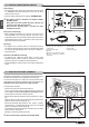
5.4 INSTALLING THE Y-ELEMENT (OPTIONAL)
• Ducting of heat to adjoining rooms is at the user’s discretion.
• The Y-element should be attached to the fan outlet.
• Proceed as follows:
- disconnect from the main power supply before opening the appliance;
- remove the stove rear panel;
- pull out the hose from the fan outlet by loosening the clip which holds
it in place (Fig. 43);
- shorten the hose (Fig. 44) connected to the stove front outlet by about
ve cm;
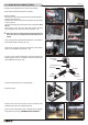
- attach a piece of hose 10 cm long onto the Y-element, noting the
arrow stamped on the Y-element, as shown in gures 45 - 49;
a Take note of the arrow stamped on the Y-element. The direction
of the arrow does not correspond to the actual direction of air
outow.
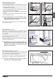
- connect the previously removed and shortened hose to the branch of
the Y-element with the arrow (Fig. 46 - 49);
- fasten the 10 cm piece of hose onto the Y-element, at the fan outlet,
using the clips provided in the kit (Fig. 47 - 49);
- t a piece of hose onto the remaining free outlet of the Y-element of
suitable length to reach the chased duct, and secure with the hose
clip provided in the kit (Fig. 48 - 49);
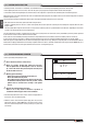
- remove the knockout from the rear panel (Fig. 50);
- ret the rear panel;
- move the stove closer to the wall (Fig. 51) and, using the hose clips
provided, x the hose to the chased duct (Fig. 52);
- place the stove in the desired location, complying with the minimum
safety distances (see section “MINIMUM SAFETY DISTANCES”).
Fig. 43 Fig. 44
Fig. 45 Fig. 46
Fig. 47 Fig. 48
DT2032896-00 DT2032897-00
PIPE SECTION L=10 cm
MULTIFUOCO
MOTOR
REAR PANEL
Y-ELEMENT
REAR
OUTLET
FRONT
OUTLET
Fig. 49
Fig. 50
Fig. 51 Fig. 52
DT2030180-00 DT2030181-00
H07031310 / DT2002112 – 00
27
English
DT2032892-00 DT2032893 -00
DT2032894-00 DT2032895-00
DT2032898-01
DT2032899-00