
Operation Manual
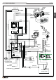


Pursuant to current regulations on the safety of electrical equipment, you must contact your dealer or a qualied electrician for all and any work
connected with installation, maintenance or servicing that involves access to electrical parts.
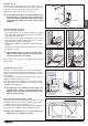
Cladding
• Having completed assembly of the stove and installed any external room thermostat, proceed with assembly of the stove cladding, referring to the
ceramic cladding instruction booklet provided with the stove.
5.0 INSTALLATION
• Thanks to Piazzetta technology and R&D, this pellet stove offers the
advantages of the “Multifuoco system”, a system EXCLUSIVE to and
PATENTED by Gruppo Piazzetta S.p.A., a true innovation in the eld of
pellet stoves.
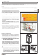
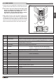
• The “Multifuoco system” revolutionises all methods of heat circulation
currently in use in pellet stoves: the heat produced by the rebox is
not only circulated from the lower part of the stove into the room, but
hot air can also be ducted via Ø 3” / (Ø 75 mm) hoses to adjoining
rooms (Fig. 26).
This exclusive oor-standing heat distribution system offers notable
advantages: even spread of temperatures (Fig. 25).
The hot air produced is propelled by two fans and distributed via the
grille at the back of the stove.
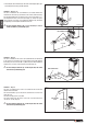
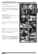
• The front grill is equipped with two deectors (Fig. 27) to change the
direction of the heat current as it exits the front of the stove. To deect
the heat current in the desired direction simply adjust the angle of the
deectors (Fig. 28) using the lever provided (Fig. 29).
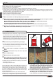
Instructions for ducting the hot air
• The fan kit, which propels hot air into the room, can be tted with two
Y-elements (one for each motor) which effectively allow the hot air
ow to be doubled up, directing it via a hose also to the rear of the
stove, from where it can then be ducted to adjoining rooms.
a Do not install more than two Y-elements in the stove otherwise
there could be problems of overheating.
• Some examples of possible installation are given below as well as
examples of how to duct the hot air in order to heat other rooms. Such
examples are given purely for demonstration purposes; best efciency
can be obtained using Ø 3” / (Ø 75 mm) coated ducting in accordance
with instructions given in the sub-paragraph “Wall and oor ducting”
and with a maximum total hose length of 32.8’ / (10 m).
This length consists of the sum of the single lengths of hoses for each
fan.
a It is of fundamental importance that when ducting heat from
the rear of the stove, the outlet vents near the stove or the
Y-element must not be closed in order to avoid overheating.
In cases where only one rear outlet from the fan is envisaged,
the outlet vent must always be kept open.
DT2012382-00
5.1 MULTIFUOCO SYSTEM
Fig. 25
Fig. 26
Fig. 27
Deectors
Fig. 28 Fig. 29
H07032120 / DT2002308 – 00
23
English
DT2010144-02
DT2010071-05
DT2030163-00
DT2030162-00
DT2030610-01
DT2030221-01 DT2030223-01