
Operation Manual
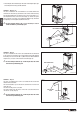


• The examples show the ducting of two fans. Each diagram gives just
one example of the many possible solutions.
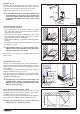
Solution 1 - Fig. 30 - 31:
The stove is installed in the room which is to be heated, with the hot
air directed to the front only, as when the stove arrives from the factory
(Fig. 30). Alternatively the air can ow to the rear by connecting a 3” /
(75 mm) diameter hose to the fan outlets (Fig. 31). In this set-up the
stove heats the room where it is installed by radiation only, and heats
the adjoining room through the ductwork to the rear.
a For the example shown in g. 31 it is necessary to use an
outlet vent which is permanently open.
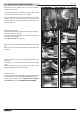
Solution 2 - Fig. 32:
The stove is installed in the room to be heated with the hot air ducted
to the front by one fan and to the rear by another fan thereby allowing
the heating of a second room. A Ø 3” / (Ø75 mm) hose with a maximum
length of 50’ / (15 m) is connected to the fan outlet (Fig. 32).
a For the example shown in g. 32 with single duct, the outlet
vent must be permanently open.
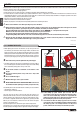
Solution 3 - Fig. 33:
The stove is installed in the room to be heated and the hot air ow
ducted in three directions.
A Y-element doubles up one fan outlet to duct the hot air to the front
and to the rear.
The other fan has just one rear outlet.
The total length of the two hoses on the two rear outlets must not
exceed 50’ / (15 m). (Fig. 33).
a For the example shown in g. 33 with single duct, the outlet
vent must be permanently open.
Non-closable vents
4’ / (1 m)
Non-closable vents
50’ / (15 m)
Non-closable
vents
10’ / (3 m)
40’ / (12 m)
Fig. 30
Fig. 31
Fig. 32
Fig. 33
H07032120 / DT2002308 – 00
24
English
DT2030216-00
DT2030217-00
DT2030218-01
DT2030219-01