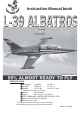
Instruction Manual book ITEM CODE:BH 141 SPECIFICATION Wingspan: Length : Weight : 1,450mm 1,860 mm 4.3-4.6 kg 57.09 in. 73.23 in. 9.46-10.12 Lbs. Parts listing required (not included). Radio : 08 channels. Servo : 08 size (29 x 13 x 30) mm. EDF: 90MM MIDI - FAN EVO/HET 650-68 -1.500 Battery: 8S-LIPO-29,6V-6,000mAh Speed control: 120A Electric gear retracts and nose gear retract 10Lb(5kg). Not including electric gears (only including oleo struts) Made in Vietnam.
L-39 ALBATROS Item code: BH141 Instruction Manual . This instruction manual is designed to help you build a great flying aeroplane. Please read this manual thoroughly before starting assembly of yourL-39 ALBATROS. Use the parts listing below to identify all parts. WARNING. Please be aware that this aeroplane is not a toy and if assembled or used incorrectly it is capable of causing injury to people or property. WHEN YOU FLY THIS AEROPLANE YOU ASSUME ALL RISK & RESPONSIBILITY.
L-39 ALBATROS Item code: BH141 . Instruction Manual Caution: this model is not a toy! If you are a beginner to this type of powered model, please ask an experienced model flyer for help and support. If you attempt to operate the model without knowing what you are doing you could easily injure yourself or somebody else. Please keep your safety and well-being in mind at all times.
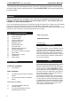
L-39 ALBATROS Item code: BH141 Instruction Manual . REPLACEMENT LARGE PARTS A .Fuselage. B. Wing panel (B1,B2). C. Horizontal stabilizer(D1,D2). D. Vertical stabilizer. E. Carbon tube wing dihedral brace. F. Carbon tube Horizontal stabilizer. G. Decal sheet. K.Pilot REPLACEMENT SMALL PARTS 1.Oleo struts retracts. 3.Plastic parts of tail fuselage. 2.Oleo strut retract nose gear. 4.Plywood of nose gear 4 5.
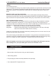
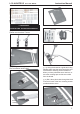
L-39 ALBATROS Item code: BH141 Instruction Manual . Servo tray. I. AILERON. 1.INSTALLING THE AILERON SERVOS. 1) Install the rubber grommets and brass eyelets onto the aileron servos. Servo tray. Bottom side. Secure. Aileron Flap 2) Using a modeling knife, remove the covering at possition show below. Servo tray. 3) Using the thread as a guide and using masking tape, tape the servo lead to the end of the thread: carefully pull the thread out.
L-39 ALBATROS Item code: BH141 Instruction Manual . 5. Instal servo tray with aileron servo into the wing as same as picture below. INSTALLING THE AILERON LINKAGES. Installing the aileron linkages as pictures below. 2x10mm. M2 60 mm. Secure. Repeat the procedure for the other wing half. INSTALLING THE AILERON CONTROL HORN. Aileron control horn A+B Epoxy PLUS glue Bottom side Aileron. Aileron control horn 6 Repeat the procedure for the other wing half.
L-39 ALBATROS Item code: BH141 Instruction Manual . II. FLAP Secure 1.INSTALLING THE FLAP SERVO Flap. servo tray. Electric wire. Electric wire. thread Repeat the procedure for the other wing half. 2.INSTALLING THE FLAP CONTROL HORN. Install flap control horn as same as picture below. Control horn Flap. 2x10mm.
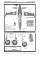
L-39 ALBATROS Item code: BH141 Instruction Manual . Bottom side. Aileron. A+B Epoxy PLUS glue Flap. Repeat the procedure for the other wing half. INSTALLING ELECTRIC GEAR RETRACTS. Control horn of the flap. PARTS REQUIRED 3.INSTALLING THE FLAP LINKAGES. Installing the flap linkages as pictures below. M2 60 mm. (Electric Not Included.) Only including oleo struts. 3x15mm.
L-39 ALBATROS Item code: BH141 . Instruction Manual 4x12mm Secure. 3x15mm Bottom side Secure. Repeat the procedure for the other gear. INSTALLING ELECTRIC EDF-90MM.
L-39 ALBATROS Item code: BH141 . Instruction Manual Bottom side Secure. Open .Plastic parts of tail fuselage.
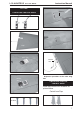
L-39 ALBATROS Item code: BH141 Instruction Manual . Horizontal stabilizer installation . See picture below. Bottom side Servo tray A+B Epoxy PLUS glue. Left side HORIZONTAL STABILIZER. ELEVATOR SERVO INSTALLATION. 1. Install the rubber grommets and brass collets into the elevator servo. Test fit the servo into the servo tray. 2. Mount the servo to the tray using the mounting screws provided with your radio system. 2x10mm. Right horizontal stabilizer Secure.
L-39 ALBATROS Item code: BH141 Instruction Manual . Left horizontal stabilizer Secure. ELEVATOR CONTROL HORN INSTALLATION. Elevator control horn install as same as the way of aileron control horn. Please see pictures below. Control horn of elevator. Elevator pushrod Left side. Bottom side A+B Epoxy PLUS glue. Right side Right side. 8 mm Elevator control horn ELEVATOR PUSHROD INSTALLATION. Elevator pushrod install as same as the way of aileron pushrod. M2 12 60 mm. carbon tube.
L-39 ALBATROS Item code: BH141 Instruction Manual . Left side Epoxy glue. Right side. C/A glue. Left side. Top side. Epoxy glue. Bottom side. Elevator pushrod C/A glue.
L-39 ALBATROS Item code: BH141 Instruction Manual . VERTICAL INSTALLATION See picture below: 2x10mm. Secure. RUDDER CONTROL HORN INSTALLATION. Rudder control horn install as same as the way of aileron control horn. Please see pictures below. Rudder servo install as same as method of elevator servo. See picture below: Control horn of Rudder. Rudder servo A+B Epoxy PLUS glue. Control Rudder.
L-39 ALBATROS Item code: BH141 . Instruction Manual RUDDER PUSHROD INSTALLATION. Rudder pushrod install as same as the way of aileron pushrod. 60mm. Epoxy glue Rudder pushrod. C/A glue. Top side. Top side. Rudder pushrod.
L-39 ALBATROS Item code: BH141 . Instruction Manual Top side Secure 3x10mm. INSTALLING ELECTRIC NOSE GEAR RETRACT. See picture below: ( Electric Not Included.) Only Including Oleo Strut Nose Gear. 2x8mm 3x10mm 16 3x15mm Secure 2x8mm.
L-39 ALBATROS Item code: BH141 . Instruction Manual wire cable. INSTALLING SERVO NOSE GEAR. See picture below: Servo nose gear wire cable. Open. wire cable.
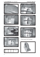
L-39 ALBATROS Item code: BH141 . Instruction Manual 2. Wrap the receiver and battery pack in the protective foam to protect them from vibration. Use a rubber band or masking tape to hold the foam in place. Servo nose gear 3. Position the battery pack and receiver is as picture below. Do not permanently secure the receiver and battery until after balancing the model. 4. Using a 2mm drill bit, drill a hole through the side of the fuselage, near the receiver, for the antenna to exit. Rudder cable.
L-39 ALBATROS Item code: BH141 Instruction Manual . Receiver. INSTALLING COCKPIT FUSELAGE . See picture below: Pilot Top side WING ATTACHMENT. 1.Locate the carbon tube wing dihedral brace. carbon tube. 12 mm 510mm.
L-39 ALBATROS Item code: BH141 . 2. Attach the carbon tube into the fuselage. Instruction Manual 3.Insert two wing panels as pictures below. Bottom side Bottom side Left wing. Secure. Secure. Right wing. 20 Bottom side.
L-39 ALBATROS Item code: BH141 Instruction Manual . Top side *If possible, first attempt to balance the model by changing the position of the receiver battery and receiver. If you are unable to obtain good balance by doing so, then it will be necessary to add weight to the nose or tail to achieve the proper balance point. BALANCING. 1) It is critical that your airplane be balanced correctly. Improper balance will cause your plane to lose control and crash.
L-39 ALBATROS Item code: BH141 . PRE-FLIGHT CHECK. 1) Completely charge your transmitter and receiver batteries before your first day of flying. 2) Check every bolt and every glue joint in your plane to ensure that everything is tight and well bonded. 3) Double check the balance of the airplane. 4) Check the control surface. 5) Check the receiver antenna . It should be fully extended and not coiled up inside the fuselage. 6) Properly balance the propeller.