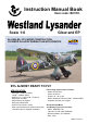
Instruction Manual Book Item code: BH170. Scale 1:6 Glow and EP ALL BALSA - PLY WOOD CONSTRUCTION. COVERED IN A HEAT-SHRINK FILM WITH PRINTED. 95% ALMOST READY TO FLY SPECIFICATION: - Wingspan: 2,540mm (100in). Length: 1,600mm (63in). Weight: 6.8 - 7.1kg (14.96 - 15.62 lbs). Wing area: 68.6 dm2. Wing loading: 99.13g/dm2. Wing type: Naca Airfoil. Servo mount: 42mm x 21mm. Gear type: Aluminium Hi-grade for main gear and spring wire for tail gear (included).
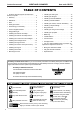
Instruction manual WESTLAND LYSANDER Item code: BH170 TABLE OF CONTENTS 4 Symbols used throughout this instruction 4 Installing the main gear . . . . . . . . . . . . . . . . 17 manual, comprise: . . . . . . . . . . . . . . . . . . . . . . . . 2 4 Warranty . . . . . . . . . . . . . . . . . . . . . . . . . . . . . 3 4 Disclaimer . . . . . . . . . . . . . . . . . . . . . . . . . . . . 3 4 Note . . . . . . . . . . . . . . . . . . . . . . . . . . . . . . . . 3 4 Safety precaution . . . . . . . . . . . . . .
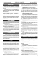
Instruction manual WESTLAND LYSANDER WARRANTY Black Horse Model guarantees the component parts in this kit to be free from defects in both material and workmanship at the date of purchase by the purchaser. This warranty does not cover cosmetic damage or damage due to acts of God, accident, misuse, abuse, negligence, commercial use, or modification of or to any part of the Product.
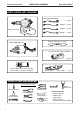
Instruction manual WESTLAND LYSANDER Item code: BH170 PARTS LISTING (NOT INCLUDED). Servo extension leads. ................. 2 pcs. 540mm .... 2 pcs. 220mm .... 4 pcs. Engine: 33cc Gas. 190mm ..... 2 pcs. Propeller. Suit with your engine. Motor: RIMFIRE.1.60 LiPo. 6S - 22.2V- 4,000 - 5,500mAh. 2 Packs 8 servos. Size: (39.9 x 20.1 x 38.1)mm. Torque servos: 7.92kg/cm - 9.43kg/cm. ESC: .120A ....... 1 pcs. TOOLS & SUPPLIES NEEDED. 10 9 8 7 6 5 4 3 2 1 Straight edge ruler.
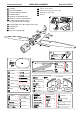
Instruction manual WESTLAND LYSANDER 1 2 3 4 5 6 : Fuselage. : Wing panel (2a, 2b). : Horizontal stabilizer (3a, 3b). : Vertical stabilizer : Aluminium wing dihedral brace. : Aluminium tube horizontal stabilizer 7 : Cockpit fuselage (7a, 7b: Canopy, 7c: Pilot, 7d: Top hatch fuselage). 8 9 10 11 12 13 14 15 Item code: BH170 : Wood - motor mount : Aluminium landing gear (13a, 13b). : Wheel pants (14a, 14b). : Wheels. 7 : Cowling. : Wing strut set (11a, 11b).
Instruction manual WESTLAND LYSANDER Item code: BH170 WING PLASTIC LIGHT C.A C.A INSTALLING THE AILERONS AND FLAPS.
Instruction manual WESTLAND LYSANDER 1) Test fit the ailerons to the wing with the hinges. If the hinges don’t remain centered, stick a pin through the middle of the hinge to hold it in position. Item code: BH170 C.A Temporary pin to keep hinge centered. 1 2 C.A Warning! Make certain the hinges are adequately secured with glue. if they come loose in flight accidents may result. 2) Apply drops of thin CA to the top and bottom of each hinge. Do not use CA accelerator.
Instruction manual WESTLAND LYSANDER 2 x 10mm Screw Item code: BH170 Warning! - - - - 16 4 4 Flap Aileron Aileron and flap servos. 90o 60o 2mm approx.16mm 2 For Flap. 1.5mm 2 For Flap. For Aileron. 2x10mm Screw For Aileron. Screw 2mm 1.5mm 1.5mm For Aileron. 1 Tie the string. 2 Pull out servo cord with string. 2x10mm 1 Bottom view 2 INSTALLING THE CONTROL HORNS AND LINKAGES.
Instruction manual WESTLAND LYSANDER Item code: BH170 Horn Horn 3x25mm 3x25mm 3mm Nut Spring M3 3x12mm Secure Push rod Horn Servo arm 9
Instruction manual WESTLAND LYSANDER Item code: BH170 INSTALLING THE FUSELAGE SERVOS 1) Install the rubber grommets and brass collets into the elevator, rudder and throttle servos. Test fit the servos into the servo tray. Trim the tray if necessary to fit your servos. 2) Mount the servo to the tray using the mounting screws provided with your radio system. o 90 4 2mm 2mm 2mm approx.
Instruction manual WESTLAND LYSANDER Item code: BH170 INSTALLING THE ENGINE MOUNT THERE ARE TWO OPTIONS: 1. ELECTRIC MOTOR 2. ENGINE MOUNT.
Instruction manual WESTLAND LYSANDER Item code: BH170 Zip tie ESC 5 mm Spring Washer 10x45mm 5mm Washer 5x70mm 152mm OPTION 2: INSTALLING THE ENGINE INSTALLING THE FUEL TANK. 1) The stopper has been pre-assembled at the factory. 2) Using a modeling knife, cut one length of silicon fuel line (the length of silicon fuel line is calculated by how the weighted clunk should rest about 8mm away from the rear of the tank and move freely inside the tank).
Instruction manual Be sure to equip air vent pipe. WESTLAND LYSANDER Not included. Tygon tubing (Gas). And silicone tubing (Methanol). To carburetor fuel inlet Tubing for re-fuelling Item code: BH170 Do not secure the tank into place permanently until after balancing the airplane. You may need to remove the tank to mount the battery in the fuel tank compartment. 9) Secure the fuel tank. 5mm (see front view of fuel tank). Insert and tighten the screw. 5) Test fit the stopper assembly into the tank.
Instruction manual WESTLAND LYSANDER Item code: BH170 152mm Pushrod choke Pushrod Gas INSTALLING THE THROTTLE Connector - - - - 1 14 direction. When the throttle stick is moved forward from idle to full throttle, the throttle barrel should also open and close using this motion. If not, reverse the direction of the servo, using the transmitter.
Instruction manual WESTLAND LYSANDER 4x4mm 2x10mm Linkage stopper Pushrod wire Item code: BH170 Adjust the throttle input (transmitter throttle stick), throttle trim movement and the carburattor opening to the suitable position and screw in the 4x4mm set screw. Screw 2mm Fuselage top side Throttle servo MOUNTING THE COWL 1) Remove the muffler and needle valve assembly from the engine. Slide the fiberglass cowl over the engine.
Instruction manual WESTLAND LYSANDER Item code: BH170 Enlarging the holes through the cowl will prevent the fiberglass from splitting when the mounting screws are installed. 6) Slide the cowl back over the engine and secure it in place using four screws. 7) Install the muffler. Connect the fuel and pressure lines to the carburator, muffler and fuel filler valve. Tighten the screws completely.
Instruction manual WESTLAND LYSANDER Item code: BH170 INSTALLING THE MAIN GEAR 115mm Wheels. 5x50mm Cap Screw ----2 5mm Nut - - 6 5mm Washer - - - - 10 4mm Spring Washer -------4 4x20mm Cap Screw -----4 3 x 10mm Screw -----4 4mm Washer -------4 Install and secure the wheel.
Instruction manual WESTLAND LYSANDER Item code: BH170 Secure the gear to the fuselage. Fuselage Bottom side. 4x20mm Screw 3x10mm 3x10mm 2.
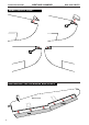
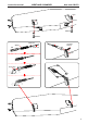
Instruction manual WESTLAND LYSANDER Item code: BH170 INSTALLING THE TAIL GEAR 4mm Colar - - 1 3x15mm Screw -----2 Fuselage Bottom side Secure 3x15mm Screw 2.5mm Fuselage top side INSTALLING HORIZONTAL STABILIZER 1) Elevators are installed the same way as the aileron before (see page 6).
Instruction manual WESTLAND LYSANDER Item code: BH170 - Attach the aluminium tube into the fuselage. - Attach the stabilizer to the fuselage.
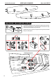
Instruction manual WESTLAND LYSANDER Item code: BH170 Connectors are installed the same way as the throttle (see page 15). Fuselage top side Elevator pushrod Elevator servo Connector Elevator servo Elevator servo Connector INSTALLING VERTICAL STABILIZER 100mm Push rod ---1 3x25mm Cap Screw -----1 Spring - - - 1 3x12mm Cap Screw ------1 Horn - - - 1 ----1 Connector ------1 1) Rudder are installed the same way as the aileron before (see page 6).
Instruction manual WESTLAND LYSANDER Item code: BH170 Rudder C.
Instruction manual WESTLAND LYSANDER Item code: BH170 Connectors are installed the same way as the throttle (see page 15). Connector Rudder pushrod Rudder o 90 Rudder servo Fuselage top side Connector Rudder servo Rudder servo INSTALLING THE SWITCH, RECEIVER AND BATTERY. 1) Plug the servo leads and the switch lead into the receiver. You may want to plug an aileron extension into the receiver to make plugging in the aileron servo lead easier when you are installing the wing.
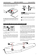
Instruction manual WESTLAND LYSANDER Item code: BH170 OFF Switch ON Fuselage top side Switch Receiver Battery Zip tie Battery INSTALLING COCKPIT FUSELAGE Cut B Position the canopy so the rear frame on the canopy is aligned with the rear edge of the cockpit opening. Use canopy glue to secure the canopy to the canopy hatch. Use low-tack tape to hold the canopy in position until the glue fully cures. Wrap the tape completely around the canopy hatch.
Instruction manual WESTLAND LYSANDER Item code: BH170 Open/Close Canopy glue Adhesive tape.
Instruction manual WESTLAND LYSANDER Item code: BH170 Adhesive tape. Adhesive tape.
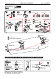
Instruction manual WESTLAND LYSANDER Item code: BH170 3x12mm Screw 3x12mm Screw Bottom view INSTALLING THE WING TO THE FUSELAGE 19x542mm Aluminium tube. ----1 *** Test fit the aluminium tube dihedral brace into each wing haft. The brace should slide in easily. If not, use 220 grit sand around the edges and ends of the brace until it fits properly. Attach the aluminium tube into the fuselage. Aluminium tube.
Instruction manual WESTLAND LYSANDER Attach the wings to the joiner tube and secure the wing panels to the fuselage. Main wing must be inserted and attached completely before fixing with screw.
Instruction manual WESTLAND LYSANDER Item code: BH170 29
Instruction manual WESTLAND LYSANDER INSTALLING THE PROPELLER 30 Item code: BH170
Instruction manual WESTLAND LYSANDER BALANCING 1) It is critical that your airplane be balanced correctly. Improper balance will cause your plane to lose control and crash. THE CENTER OF GRAVITY IS LOCATED 93MM BACK FROM THE LEADING EDGE OF THE WING. AT THE FUSELAGE. BALANCE A PLANE UPSIDE DOWN WITH THE FUEL TANK EMPTY. 2) Mount the wing to the fuselage. Using a couple of pieces of masking tape, place them on the top side of the wing 93mm back from the leading edge, at the fuselage sides.
Instruction manual WESTLAND LYSANDER Item code: BH170 FOR YOUR RADIO INSTALLATION BASIC CONNECTION FOR AIRPLANE AND ADJUSTMENT OF SERVOS Example of connection For more information, refer to radio system instruction manual. Follow instruction manual of Engine and Battery.
Instruction manual WESTLAND LYSANDER Item code: BH170 MAIN GEAR DIMENSIONAL DETAIL 35mm 23mm 66.
I/C FLINGT WARNINGS NEVER fly near power lines,aerials or other dangerous areas including airports, motorways etc. ALWAYS adjust the engine from behind the propeller, and do not allow any part of your body to be in line with the propeller. Always operate in open areas, away from factories, hospitals, schools, buildings and houses etc. NEVER fly your aircraft close to people or built up areas. DO NOT dispose of empty fuel containers on a fire, this can lead to an explosion.
I/C FLINGT GUIDELINES When ready to fly, first extend the transmitter aerial. Operate the control sticks on the transmitter and check that the control surfaces move freely and in the CORRECT directions. ALWAYS land the model INTO the wind, this ensures that the model lands at the slowest possible speed. OFF - ON OFF - ON OFF - ON Switch on the transmitter. Check that the transmitter batteries have adequate power. Switch off the receiver. OFF - ON OFF - ON OFF - ON Switch on the receiver.