Instruction Manual book SPECIFICATION Wingspan : Length : Weight : Radio : Servo : Engine : 1,500 mm 1,160 mm 2.4 kg 04 channels. 05 servos. 40 - 46 52 59 in. 46 in. 5.28 Lbs. 2 stroke 4 stroke Made in Vietnam.
SPEED AIR-40 _Item code:BH08. Instruction Manual. This instruction manual is designed to help you build a great flying aeroplane. Please read this manual thoroughly before starting assembly of your SPEED AIR-40. Use the parts listing below to identify all parts. WARNING. Please be aware that this aeroplane is not a toy and if assembled or used incorrectly it is capable of causing injury to people or property. WHEN YOU FLY THIS AEROPLANE YOU ASSUME ALL RISK & RESPONSIBILITY.
SPEED AIR-40 _Item code:BH08. Instruction Manual. Caution: this model is not a toy! If you are a beginner to this type of powered model, please ask an experienced model flyer for help and support. If you attempt to operate the model without knowing what you are doing you could easily injure yourself or somebody else. Please keep your safety and well-being in mind at all times.
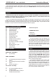
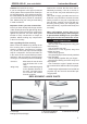
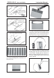
SPEED AIR-40 _Item code:BH08. Instruction Manual. REPLACEMENT SMALL PARTS 3x15mm 3x12mm 1. Main landing gear. 2. Nose gear 3.Steering arm. 4. Fuel Tank. 5. Wheels. 6. Spinner. Top side 7. Plastic parts for elevator and rudder pushrod. Bottom side. SERVO INSTALLATION. INSTALLING THE AILERON SERVOS. 1. Install the rubber grommets and brass eyelets onto the aileron servo.
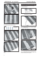
SPEED AIR-40 _Item code:BH08. Instruction Manual. Remove covering. Cut the covering away from the slot. Servo tray Temporary pin to keep hinge centered. 3. Drill 1,5mm pilot holes through the block Assemble then apply drops of thin C/A to center of hinge,on both sides. of wood for each of the four mounting screws provided with the servo. Install servo into aileron servo tray as same as picture below. 4.
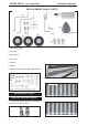
SPEED AIR-40 _Item code:BH08. Instruction Manual. INSTALLING THE AILERON CONTROL HORN. Electric wire. Install aileron control horn as same as picture below. Thread. 2 x16mm. Control horn of Aileron 5. Instal servo tray with aileron servo into the wing as same as picture below. 2 x 10 mm. 1. Using a ruler & pen to draw a straight line as below picture. Secure. Mark line. Bottom side. Repeat the procedure for the other wing half. 6 2. Drill through 1.
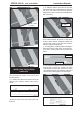
SPEED AIR-40 _Item code:BH08. Instruction Manual. 3. Plug the aileron servo into the receiver and center the servo. Install the servo arm onto the servo. The servo arm should be perpendicular to the servo and point toward the middle of the wing. Drill a hole 1.5mm Secure Bend and cut after. 4. Locate one nylon servo arm, and using wire cutters,remove all but one of the arms. Using a 2mm drill bit, enlarge the third hole out from the center of the arm to accommodate the aileron pushrod wire. 5.
SPEED AIR-40 _Item code:BH08. Instruction Manual. A+B Epoxy PLUS Aileron pushrod. Bottom side. 3x15mm Repeat the procedure for the other wing half. MAIN GEAR INSTALATION. PARTS REQUIRED A+B Epoxy PLUS Glue 3x15mm Remove covering. Secure.
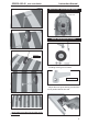
SPEED AIR-40 _Item code:BH08. Instruction Manual. INSTALLING THE ENGINE MOUNT. Front view. NOSE GEAR INSTALLATION. Secure. Installing steering arm as follow Steering arm. Adjust the nose gear steering arm until the arm is parallel with the fire wall. Repeat the procedure for the other main gear wheel.
SPEED AIR-40 _Item code:BH08. Instruction Manual. Secure. Front view. Secure.
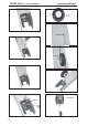
SPEED AIR-40 _Item code:BH08. Instruction Manual. INSTALLING THE ENGINE. Locate the long piece of wire used for the throttle pushrod. One end of the wire has been pre-bend in to a “Z” bend at the factory. This “Z” bend should be inserted into the throttle arm of the engine when the engine is fitted onto the engine mount. Fit the engine to the engine mount using the screws provided. Throttle wire. 3x 20mm Mark point. Secure. Left side. Drill a hole 2.5mm diameter FUEL TANK.
SPEED AIR-40 _Item code:BH08. 3) Carefully bend the second nylon tube up at a 45 degree angle (using a cigarette lighter). This tube will be the vent tube to the muffler. 4) Carefully bend the third nylon tube down at a 45 degree angle (using a cigarette lighter). This tube will be vent tube to the fueling valve. Instruction Manual. 6) When satisfied with the alignment of the stopper assembly tighten the 3mm x 20mm machine screw until the rubber stopper expands and seals the tank opening.
SPEED AIR-40 _Item code:BH08. Instruction Manual. Tie wrap Throttle servo INSTALLING THE THROTTLE SERVO. Throttle wire. 1. Install one adjustable metal connector through the third hole out from the center of one servo arm, enlarge the hole in the servo arm using a 2mm drill bit to accommodate the servo connector. Remove the excess material from the arm. secure. After installing the adjustable metal connector apply a small drop of thin C/A to the bottom nut.
SPEED AIR-40 _Item code:BH08. Instruction Manual. INSTALLING THE SPINNER. 3x 12mm Install the spinner backplate, propeller and spinner cone. The spinner cone is held in place using two 3mm x 12mm wood screws. ELEVATOR INSTALLATION. SERVO INSTALLATION. 1. Install the rubber grommets and brass collets into the elevator servo. Test fit the servo into the servo tray. 2. Mount the servo to the tray using the mounting screws provided with your radio system. Elevator servo. Elevator servo. Secure.
SPEED AIR-40 _Item code:BH08. HORIZONTAL STABILIZER INSTALLATION. See pictures below: Instruction Manual. 1. Using a modeling knife, cut away the covering from the fuselage for the stabilizer and remove it. Top side Bottom side Cut the covering away from the slot. Remove covering. Temporary pin to keep hinge centered. Assemble then apply drops of thin C/A to center of hinge,on both sides.
SPEED AIR-40 _Item code:BH08. Instruction Manual. Bottom side. 3. With the stabilizer held firmly in place, use a pen and draw lines onto the stabilizer where it and the fuselage sides meet. Do this on both the right and left sides and top and bottom of the stabilizer. When cutting through the covering to remove it, cut with only enough pressure to only cut through the covering itself. Cutting into the balsa structure may weaken it. 5.
SPEED AIR-40 _Item code:BH08. 7) After the epoxy has fully cured, remove the masking tape or T-pins used to hold the stabilizer in place. Carefully inspect the glue joints. Use more epoxy to fill in any gaps that may exist that were not filled previously and clean up the excess using a paper towel and rubbing alcohol. Instruction Manual. ELEVATOR CONTROL HORN INSTALLATION. Elevator control horn install as same as the way of aileron control horn. Please see pictures below. Control horn of elevator.
SPEED AIR-40 _Item code:BH08. 2) Install control horn as same as picture below. Instruction Manual. Top side Control horn of elevator. ELEVATOR PUSHROD INSTALLATION. Elevator servo. Elevator pushrod install as same as the way of aileron pushrod. Elevator pushrod. Elevator pushrod. Bottom side Elevator pushrod. 18 Elevator pushrod.
SPEED AIR-40 _Item code:BH08. Instruction Manual. Cut the covering away from the slot. RUDDER SERVO INSTALLATION. Rudder servo install as same as method of elevator servo. See picture below: Temporary pin to keep hinge centered. Rudder servo. Assemble then apply drops of thin C/A to center of hinge,on both sides. Rudde r servo . VERTICAL INSTALLATION.
SPEED AIR-40 _Item code:BH08. Instruction Manual. 4) Now, remove the vertical stabilizer and Remove covering. using a modeling knife, carefully cut just inside the marked lines and remove the film of the vertical stabilizer. Just as you did with the horizontal stabilizer, make sure you only press hard enough to cut the film, not the balsa vertical stabilizer. Remove covering. 2) Slide the vertical stabilizer into the slot in the top of the fuselage.
SPEED AIR-40 _Item code:BH08. Instruction Manual. Epoxy glue. C/A glue. 6) When you are sure that everything is a aligned correctly, mix up a generous amount of 30 minute epoxy. Apply a thin layer to the slot in the mounting platform and to the vertical stabilizer mounting area. Apply epoxy to the lower rudder hinge. Set the stabilizer in place and re-align. Double check all of your measurements once more before the epoxy cures.
SPEED AIR-40 _Item code:BH08. Instruction Manual. Secure. Rudder pushrod. connector. servo arm Rudder control horn. Nose gear pushrod. Bend and cut Rudder pushrod. Rudder pushrod.
SPEED AIR-40 _Item code:BH08. Instruction Manual. Plastic parts of elevator and rudder pushrod. Snap keeper Cut. Secure. C/A glue. Nose gear pushrod. Elevator pushrod. Elevator pushrod. Bottom side. Rudder pushrod. Bottom side.
SPEED AIR-40 _Item code:BH08. Instruction Manual. INSTALLING THE SWITCH. 1. Cut out the switch hole using a modeling knife. Use a 2mm drill bit and drill out the two mounting holes through the fuselage side. Tie wrap. 2. Secure the switch in place using the two machine screws provided with the radio system. Switch Battery. Switch Switch Receiver. WING ATTACHMENT. 1.Locate the aluminium wing dihedral brace. INSTALLING THE RECEIVER AND BATTERY. 1.
SPEED AIR-40 _Item code:BH08. Instruction Manual. Right side. Secure. Secure. See picture wing attach to fuselage. Installing the fuselage hatch as same as picture below. Top side. Left side. 3. Insert two wing panels as pictures below.
SPEED AIR-40 _Item code:BH08. Instruction Manual. BALANCING. CONTROL THROWS. 1) It is critical that your airplane be balanced correctly. Improper balance will cause your plane to lose control and crash. 1) We highly recommend setting up a plane THE CENTER OF GRAVITY IS LOCATED 73MM BACK FROM THE LEADING EDGE OF THE WING. 2) Mount the wing to the fuselage. Using a couple of pieces of masking tape, place them on the top side of the wing 73 mm back from the leading edge, at the fuselage sides.