
Instructions


Glossary20
Copyright © 2018 Pico Technology Ltd. All rights reserved.ps5000d.en r1
4 Glossary
API. Application Programming Interface. A library of function calls that give programmers access to the
PicoScope device.
AWG. Arbitrary waveform generator. A circuit that can generate a waveform of almost any shape, as defined by
the user.
Bandwidth. The range of input frequencies over which the measured signal amplitude is no more than 3 decibels
below its true value.
Capture memory. The buffer memory is used by the oscilloscope to store data temporarily. This allows the
oscilloscope to sample data independently of the speed at which it can transfer data to the computer. The size of
the buffer memory is measured in samples.
Collection time. The time represented by the horizontal axis of the PicoScope display. On traditional
oscilloscopes, this function is often known as the timebase.
Coupling control. To switch from AC coupling to DC coupling, or vice versa, select AC or DC from the control on
the oscilloscope toolbar of the PicoScope software application. The AC setting filters out any DC component of
the input signal, and is suitable for viewing small AC signals superimposed on a DC or slowly-changing offset. In
this mode you can measure the peak-to-peak amplitude of an AC signal but not its absolute value. Use the DC
setting for measuring the absolute value of a signal.
Driver. A program that controls a piece of hardware. The driver for the PicoScope 5000D Series oscilloscopes is
supplied in the form of a 32-bit or 64-bit Windows DLL, ps5000a.dll. This is used by the PicoScope software,
and by user-designed applications, to control the oscilloscopes.
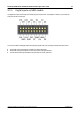
External trigger. This is the BNC connector marked Ext on the PicoScope 5000D Series (non-MSO)
oscilloscopes. It can be used as a trigger source but not as a waveform input. See also Connector information.
FlexRes
®
. The ability to reconfigure the hardware either to increase the sampling rate or the resolution. This
allows you to capture and decode fast digital signals and to look for distortion in sensitive analog signals, all
using the same oscilloscope.
Input range.The range of input voltages that the oscilloscope can measure. For example, a voltage range of ±20 V
means that the oscilloscope can measure voltages between –20 V and +20 V. Input voltages outside this range
will not be measured correctly, but will not damage the instrument as long as they remain within the protection
limits stated in the specifications.
LSB. Least significant bit. This is the smallest voltage difference that the PicoScope can distinguish and is
determined by the selected hardware resolution of the device.
Maximum sampling rate. A figure indicating the maximum number of samples the oscilloscope can acquire per
second. Maximum sample rates are usually given in MS/s (megasamples per second) or GS/s (gigasamples per
second.) The higher the sampling rate of the oscilloscope, the more accurate the representation of the high-
frequency details in a fast signal.
MS/s. Megasamples per second. Used to quantify the sampling rate of an oscilloscope.
MSO. Mixed-signal oscilloscope. An oscilloscope that has both analog and digital inputs.
PicoScope software. This software product accompanies all our oscilloscopes. Along with your PicoScope
device, it turns your PC into an oscilloscope and spectrum analyzer. You can download free updates and beta
versions of the software from www.picotech.com/downloads.
Signal generator. A built-in circuit that generates signals suitable for driving an external device under test. Its
output is the BNC connector marked Gen on the oscilloscope. See also Connector information.