
Instructions


Product information14
Copyright © 2018 Pico Technology Ltd. All rights reserved.ps5000d.en r1
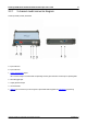
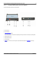
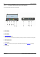
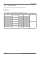
3.2.4 4-channel MSO model connector diagram
PicoScope 5442D MSO, 5443D MSO, and 5444D MSO.
A. Input channel A
B. Input channel B
C. Input channel C
D. Input channel D
1. Probe compensation output
LED: red when scope is connected but not operating. Flashes green when the oscilloscope is capturing data.
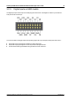
2. Digital inputs D0 to D15
3. Signal generator output
4. Ground terminal
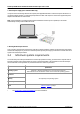
5. USB 3.0 port: connects to your PC using the Hi-Speed USB cable supplied. See Installation for powering
options.
6. DC power input