
User manual


PicoLog 1000 Series User's Guide 7
Copyright © 2009 Pico Technology Ltd. All rights reserved. pl1000.en
1.9
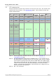
Example circuit (light)
Here is an example of a sensor circuit that you could connect to the logger.
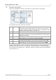
The components of the circuit are as follows:
R
1
ORP12
A light-dependent resistor of type ORP12 or similar. In the dark
this acts like a fixed resistor with a high value of 1 MW or more,
but when exposed to light its resistance drops in proportion to the
brightness of the light, down to several kW.
R
2
100 kW
A fixed resistor to limit the current through R
1
.
R
3
1 MW
The input resistance of the PicoLog Data Logger. You do not have
access to this resistor, but you may need to know its value when
designing your circuit.
C
1
Channel 1
The C1 pin on the data logger. If you are using the Pico Small
Terminal Board, use the screw terminal marked C1.
PO
+2.5 V
The power output pin on the data logger. If you are using the
Pico Small Terminal Board, use the screw terminal marked 2.5.
GND
Ground
The GND pin on the data logger. If you are using the Pico Small
Terminal Board, use any of the screw terminals marked GND.
Once you have built the circuit, connect it to the Data Logger, run the PicoScope 6
software and watch the trace on the display. When the sensor is exposed to light, the
trace should rise to almost 2.5 V. When the sensor is covered, the trace should fall to
a value close to 0 V.