PicoLog 1000 Series Programmer's Guide pl1000pg.en-1 Copyright © 2009 Pico Technology Ltd. All rights reserved.
PicoLog 1000 Series Programmer's Guide I Contents 1 Introduction .....................................................................................................................................1 1 Overview ...........................................................................................................................................1 2 Legal information .......................................................................................................................................
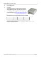
PicoLog 1000 Series Programmer's Guide 1 Introduction 1.1 Overview 1 The PicoLog 1000 Series PC Data Loggers are mediumspeed, multichannel voltage-input devices for sampling analog data using a PC. This manual explains how to use the Application Programming Interface and drivers to write your own programs to control the unit. You should read it in conjunction with the PicoLog 1000 Series User's Guide. The following PicoLog 1000 Series Data Loggers are available: Version Part No.
2 1.2 Introduction Legal information The material contained in this release is licensed, not sold. Pico Technology grants a licence to the person who installs this software, subject to the conditions listed below. Access The licensee agrees to allow access to this software only to persons who have been informed of these conditions and agree to abide by them. Usage The software in this release is for use only with Pico products or with data collected using Pico products.
PicoLog 1000 Series Programmer's Guide 1.3 3 Contact details Address: Pico Technology James House Colmworth Business Park ST. NEOTS Cambridgeshire PE19 8YP United Kingdom Phone: Fax: +44 (0) 1480 396 395 +44 (0) 1480 396 296 Email: Technical Support Sales support@picotech.com sales@picotech.com Web site: www.picotech.com Copyright © 2009 Pico Technology Ltd. All rights reserved. pl1000pg.
4 Getting started 2 Getting started 2.1 About the driver The PicoLog 1000 Series units are supplied with a kernel driver, and a DLL containing routines that you can build into your own programs. The driver is supported by the following operating systems: Windows XP (SP2 or later) Windows Vista Windows 7 Once you have installed the software, the installation directory will contain the drivers and a selection of examples of how to use the drivers. It also contains a copy of this help file in PDF format.
PicoLog 1000 Series Programmer's Guide 2.4 5 USB ADC-11 compatibility mode The PicoLog 1000 Series data loggers may be used as replacements for the USB ADC11, an 11-channel data logger previously available from Pico Technology. The 1000 Series units have all the functions of the USB ADC-11 and some extra functions, such as extra digital outputs 18 , a PWM output 20 and a sensor power output. The 1000 Series units are API-compatible with the USB ADC-11.
6 Technical reference 3 Technical reference 3.1 Capture modes Three modes are available for capturing data: BM_SINGLE: collect a single block of data and exit BM_WINDOW: collect a series of overlapping blocks of data BM_STREAM: collect a continuous stream of data BM_SINGLE is useful when you wish to collect data at high speed for a short period: for example, to collect 1000 readings in 50 milliseconds.
PicoLog 1000 Series Programmer's Guide 3.3 Driver routines 3.3.
8 3.3.2 Technical reference pl1000CloseUnit PICO_STATUS pl1000CloseUnit( short handle ) This function closes the unit. Arguments: Returns: pl1000pg.en handle: handle returned from pl1000OpenUnit pl1000OpenUnitProgress 15 PICO_OK 23 PICO_HANDLE_INVALID 23 13 or Copyright © 2009 Pico Technology Ltd. All rights reserved.
PicoLog 1000 Series Programmer's Guide 3.3.3 9 pl1000GetSingle PICO_STATUS pl1000GetSingle( short handle, PL1000_INPUTS channel, unsigned short * value ) This function returns a single sample value from the specified input channel.
10 3.3.4 Technical reference pl1000GetUnitInfo PICO_STATUS pl1000GetUnitInfo( short handle, char * string, short stringLength, short * requiredSize, PICO_INFO info ) This function returns a string containing the specified item of information about the unit. If you want to find out the length of the string before allocating a buffer for it, then call the function with string = NULL first.
PicoLog 1000 Series Programmer's Guide 3.3.5 11 pl1000GetValues PICO_STATUS pl1000GetValues( short handle, unsigned short * values, unsigned long * noOfValues, unsigned short * overflow, unsigned long * triggerIndex ) This function is used to get values after calling pl1000_run Arguments: 17 . handle: handle returned from pl1000OpenUnit pl1000OpenUnitProgress 13 or 15 values: an array of sample values returned by the function.
12 3.3.6 Technical reference pl1000MaxValue PICO_STATUS pl1000MaxValue( short handle, unsigned short * maxValue ) This function returns the maximum ADC value that the device will return. This value may be different on different models in the PicoLog 1000 Series. Arguments: handle: handle returned from pl1000OpenUnit pl1000OpenUnitProgress 13 or 15 maxValue: a location where the function will write the maximum ADC value Returns: pl1000pg.
PicoLog 1000 Series Programmer's Guide 3.3.7 13 pl1000OpenUnit PICO_STATUS pl1000OpenUnit( short * handle ) This function opens and enumerates the unit. Arguments: handle: the function will write a value here that uniquely identifies the data logger that was opened. Use this as the handle parameter when calling any other PicoLog 1000 Series API function.
14 3.3.8 Technical reference pl1000OpenUnitAsync PICO_STATUS pl1000OpenUnitAsync( short * status ) This function opens a PicoLog 1000 Series data logger without waiting for the operation to finish. You can find out when it has finished by periodically calling pl1000OpenUnitProgress 15 until that function returns a non-zero value and a valid data logger handle. The driver can support up to four data loggers. pl1000pg.
PicoLog 1000 Series Programmer's Guide 3.3.9 15 pl1000OpenUnitProgress PICO_STATUS pl1000OpenUnitProgress( short * handle, short * progress, short * complete ) This function checks on the progress of pl1000OpenUnitAsync Arguments: 14 . handle: a pointer to where the function should store the handle of the opened data logger, if the operation was successful. Use this as the handle parameter when calling any other PicoLog 1000 Series API function.
16 Technical reference 3.3.10 pl1000Ready PICO_STATUS pl1000Ready( short handle, short * ready ) This function indicates when pl1000Run samples. Arguments: has captured the requested number of 17 handle: handle returned from pl1000OpenUnit pl1000OpenUnitProgress 13 or 15 ready: TRUE if ready, FALSE otherwise Returns: pl1000pg.en PICO_OK 23 PICO_INVALID_HANDLE PICO_NOT_RESPONDING 23 23 Copyright © 2009 Pico Technology Ltd. All rights reserved.
PicoLog 1000 Series Programmer's Guide 17 3.3.11 pl1000Run PICO_STATUS pl1000Run( short handle, unsigned long no_of_values, BLOCK_METHOD method ) This function tells the unit to start capturing data. Arguments: handle: handle returned from pl1000OpenUnit pl1000OpenUnitProgress 13 or 15 no_of_values: the number of samples the unit should collect method: which method to use to collect the data, from the following list: BM_SINGLE BM_WINDOW BM_STREAM See "Capture modes Returns: 6 " for details.
18 Technical reference 3.3.12 pl1000SetDo PICO_STATUS pl1000SetDo( short handle, short do_value, short doNo ) This function controls the digital outputs DO0 to DO3 on the unit. Arguments: handle: handle returned from pl1000OpenUnit pl1000OpenUnitProgress 13 or 15 do_value: whether to switch the output on or off: 1 - turns the digital output on 0 - turns the digital output off doNo: which output to switch, from PL1000_DO_CHANNEL_0 to PL1000_DO_CHANNEL_3 Returns: pl1000pg.
PicoLog 1000 Series Programmer's Guide 19 3.3.13 pl1000SetInterval PICO_STATUS pl1000SetInterval( short handle, unsigned long * us_for_block, unsigned long ideal_no_of_samples, short * channels, short no_of_channels ) This function sets the sampling rate of the unit. The fastest possible sampling interval is 1 microsecond, when the number of samples is 8129 divided by the number of channels active and the capture mode 6 is BM_SINGLE.
20 Technical reference 3.3.14 pl1000SetPulseWidth PICO_STATUS pl1000SetPulseWidth( short handle, unsigned short period, unsigned char cycle ) This function sets the pulse width of the PWM (pulse-width modulated) output. Arguments: handle: handle returned from pl1000OpenUnit pl1000OpenUnitProgress 13 or 15 period: the required period of the PWM waveform in microseconds, from 100 to 1800 cycle: the required duty cycle as a percentage from 0 to 100 Returns: pl1000pg.
PicoLog 1000 Series Programmer's Guide 21 3.3.15 pl1000SetTrigger PICO_STATUS pl1000SetTrigger( short handle, unsigned short enabled, unsigned short auto_trigger, unsigned short auto_ms, unsigned short channel, unsigned short dir, unsigned short threshold, unsigned short hysteresis, float delay ) This function sets up the trigger, which controls when the unit starts capturing data.
22 Technical reference 3.3.16 pl1000Stop PICO_STATUS pl1000Stop( short handle ) This function aborts data collection. Arguments: Returns: pl1000pg.en handle: handle returned from pl1000OpenUnit pl1000OpenUnitProgress 15 PICO_OK 23 PICO_INVALID_HANDLE 23 13 or Copyright © 2009 Pico Technology Ltd. All rights reserved.
PicoLog 1000 Series Programmer's Guide 23 3.3.
24 pl1000pg.
PicoLog 1000 Series Programmer's Guide 3.4 Example programs 3.4.1 Introduction 25 We supply examples for the following programming languages: C 25 and C++ Delphi 25 Excel 25 LabVIEW 26 Visual Basic 26 Agilent VEE 26 3.4.2 25 C and C++ C Use the following files: pl1000.lib pl1000api.h pl1000bc.lib pl1000con.c C++ C++ programs can access all versions of the driver. If pl1000api.
26 3.4.5 Technical reference LabVIEW The routines described here were tested using LabVIEW version 4.0. While it is possible to access all of the driver routines described earlier, it is easier to use the special LabVIEW access routines if only single readings are required. The pl1000.llb library in the installation directory shows how to access these routines. To use these routines, copy pl1000.llb and pl1000.dll to your LabVIEW user. lib directory.
PicoLog 1000 Series Programmer's Guide 4 27 Glossary ADC. Analog to Digital Converter. An ADC samples analog signals and converts them to digital data for storage and processing. It is an essential component of a data logger. DLL. Dynamic Link Library. A file containing a collection of Windows functions designed to perform a specific class of operations. A DLL is supplied with the PicoLog Data Loggers to enable you to control the devices from your own programs. Driver.
PicoLog 1000 Series Programmer's Guide 29 Index pl1000Stop 22 summary 7 E 6 Excel 64-bit Windows G A Glossary ADC value, maximum 12 ADC-11 compatibility 5 Agilent VEE 26 Asynchronous operation 6 B BM_SINGLE mode 6 BM_STREAM mode 6 BM_WINDOW mode 6 C C 25 4 27 I Information on unit, obtaining Installation 4 10 L LabVIEW 26 Legal information 2 M 25 Maximum ADC value C++ 25 Capture modes BM_SINGLE 6 BM_STREAM 6 BM_WINDOW 6 Closing a unit 8 Connecting to the PC Contact details 3 12 N Ne
30 Index S Sampling interval, setting Scaling 6 SDK 5 Stopping a unit Streaming 6 19 22 T Trigger, setting 21 U Unit information, obtaining 10 USB ADC-11 compatibility 5 V Visual Basic 26 W Windows XP/Vista support 4 WoW64 pl1000pg.en 4 Copyright © 2009 Pico Technology Ltd. All rights reserved.
PicoLog 1000 Series Programmer's Guide 31 Copyright © 2009 Pico Technology Ltd. All rights reserved. pl1000pg.
Pico Technology James House Colmworth Business Park ST. NEOTS Cambridgeshire PE19 8YP United Kingdom Tel: +44 (0) 1480 396 395 Fax: +44 (0) 1480 396 296 www.picotech.com pl1000pg.en-1 12.5.09 Copyright © 2009 Pico Technology Ltd. All rights reserved.