PicoLog 1000 Series User's Guide pl1000.en-1 Copyright © 2009 Pico Technology Ltd. All rights reserved.
PicoLog 1000 Series User's Guide I Contents 1 Introduction .....................................................................................................................................1 1 Overview ...........................................................................................................................................1 2 Safety warning ...........................................................................................................................................
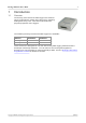
PicoLog 1000 Series User's Guide 1 Introduction 1.1 Overview 1 The PicoLog 1000 Series PC Data Loggers are mediumspeed, multichannel voltage-input devices for sampling analog data using a PC. This manual describes the physical properties of the loggers.
2 1.2 Introduction Safety warning We strongly recommend that you read the general safety information below before using your product for the first time. If the equipment is not used in the manner specified, then the protection provided may be impaired. This could result in damage to your computer and injury to yourself or others. Maximum input range The inputs of the PicoLog 1000 Series loggers are protected against overvoltages up to ±30 V.
PicoLog 1000 Series User's Guide 1.3 3 Legal information The material contained in this release is licensed, not sold. Pico Technology grants a licence to the person who installs this software, subject to the conditions listed below. Access The licensee agrees to allow access to this software only to persons who have been informed of these conditions and agree to abide by them. Usage The software in this release is for use only with Pico products or with data collected using Pico products.
4 1.4 Introduction Accessories The following items are supplied in all packages: Standard items Part no. PicoLog 1000 Series PC Data Logger PP543 (PicoLog 1012) PP544 (PicoLog 1216) MI106 DI025 DO112 USB cable Software and Reference CD-ROM USB Installation Guide The following additional items are supplied in some packages (see our website for details): Additional items Part no.
PicoLog 1000 Series User's Guide 1.6 5 Connecting the logger Before you connect your logger, you must install the software supplied on the CD. To connect the PicoLog logger, plug the cable provided into any available USB port on your PC. I/O connector: for the pin-numbering of the I/O connector, see I/O connector pins 9 . The Pico PP545 Small Terminal Board is specially designed to connect to this socket to allow you to make connections to individual wires easily without soldering.
6 1.8 Introduction Example circuit (voltage) This is how to connect a simple voltage source to the Data Logger: The components of the circuit are as follows: V Battery R 1 MW C1 Channel 1 GND Ground Any cell, battery or transducer with a voltage output in the range 0 V to +2.5 V. The input resistance of the PicoLog Data Logger. You do not have access to this resistor, but you may need to know its value when designing your circuit. The C1 pin on the Data Logger.
PicoLog 1000 Series User's Guide 1.9 7 Example circuit (light) Here is an example of a sensor circuit that you could connect to the logger. The components of the circuit are as follows: R1 ORP12 R2 100 kW R3 1 MW C1 Channel 1 PO +2.5 V GND Ground A light-dependent resistor of type ORP12 or similar. In the dark this acts like a fixed resistor with a high value of 1 MW or more, but when exposed to light its resistance drops in proportion to the brightness of the light, down to several kW.
8 Product information 2 Product information 2.1 Specifications PicoLog 1012 Maximum sampling rate 11 continuous streaming block mode [1] Buffer size 100 kS/s single-channel 1 MS/s single-channel 8k samples, shared by all channels Analog inputs 12 analog bandwidth [2] DC to 70 kHz Single-ended, unipolar input voltage range accuracy 0 to +2.5 V (at 25 °C) 11 resolution 11 11 overload protection 1 LSB 10 bits 12 bits 1% 0.
PicoLog 1000 Series User's Guide 2.2 9 I/O connector pins The I/O connector is the 25-way connector on the front of the unit. Pin numbers and signal names are as follows. See Specifications 8 for further details of input and output characteristics. Pin no. Pin name Function Shell GND 1 DO1 2 GND 3 4 5 6 7 8 9 10 11 12 13 14 15 16 17 C1 C2 C3 C4 C5 C6 C7 C8 C9 C10 C11 DO2 DO4 DO3 PO 18 PWM 19 20 21 22 23 24 25 GND GND C12 C13 C14 C15 C16 Note 1: Note 2: Note 3: Characteristics 0.
10 Product information The I/O connector pins are numbered as follows: 2.3 USB ADC-11 compatibility mode The PicoLog 1000 Series data loggers may be used as replacements for the USB ADC11, an 11-channel data logger previously available from Pico Technology. The 1000 Series units have all the functions of the USB ADC-11 and some extra functions, such as extra digital outputs 9 , a PWM output 9 and a sensor power output. They also have a faster USB interface and more advanced driver software.
PicoLog 1000 Series User's Guide 3 11 Glossary Accuracy. The closeness between measured values and true values. This is more usually expressed as the error, as a percentage of full scale, between the measured value and the true value. ADC. Analog to Digital Converter. An ADC samples analog signals and converts them to digital data for storage and processing. It is an essential component of a data logger. Analog bandwidth.
PicoLog 1000 Series User's Guide 13 Index O Overload protection Overview 1 A P Accessories 4 Accuracy 8, 11 ADC 11 ADC-11 compatibility mode Analog bandwidth 11 Analog inputs 8 8, 10 B Resolution C Contact details PC connection 8 PicoScope 5 Power output 8 PWM 11 PWM output 8 R Bandwidth 8 Block mode 8 Circuit example Compliance 8 Connections 5 8, 11 8, 11 S 6, 7 Safety warning 2 Sampling rate 8 Small Terminal Board 4 4 Specifications 8 Status LED 5 Streaming mode 8 D Digital outputs
PicoLog 1000 Series User's Guide Copyright © 2009 Pico Technology Ltd. All rights reserved. 15 pl1000.
Pico Technology James House Colmworth Business Park ST. NEOTS Cambridgeshire PE19 8YP United Kingdom Tel: +44 (0) 1480 396 395 Fax: +44 (0) 1480 396 296 www.picotech.com pl1000.en-1 12.5.09 Copyright © 2009 Pico Technology Ltd. All rights reserved.