
User manual


PicoScope 3000 A and B Series PC Oscilloscopes and MSOs User's Guide 15
Copyright © 2012 Pico Technology Limited. All rights reserved. ps3000ab.en iss3
6 Glossary
API. Application Programming Interface. A set of function calls that give
programmers access to the PicoScope 3000 A/B Series driver.
Bandwidth. The range of input frequencies over which the measured signal amplitude
is no more than 3 decibels below its true value.
Buffer size. The size of the oscilloscope buffer memory, measured in samples. In
block mode, the buffer memory is used by the oscilloscope to store data temporarily.
This allows the oscilloscope to sample data independently of the speed at which it can
transfer data to the computer.
Device Manager. Device Manager is a Windows program that displays the current
hardware configuration of your computer. For Windows XP: Right-click on 'My
Computer,' choose 'Properties', then click the 'Hardware' tab and the 'Device Manager'
button. For Windows Vista and Windows 7: From the Start Menu right-click on
'Computer', choose 'Properties', then click 'Device Manager' in the left panel.
Driver. A program that controls a piece of hardware. The driver for the PicoScope
3000 A and B Series PC Oscilloscopes and MSOs is supplied in the form of a 32-bit
Windows DLL, ps3000a.dll. This is used by the PicoScope software, and by user-
designed applications, to control the oscilloscopes.
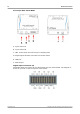
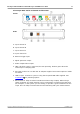
External trigger. This is the BNC connector marked EXT on the PicoScope 3000
Series PC oscilloscopes. It can be used as a trigger source but not as a waveform
input.
Maximum sampling rate. A figure indicating the maximum number of samples the
oscilloscope can acquire per second. Maximum sample rates are usually given in MS/s
(megasamples per second) or GS/s (gigasamples per second.) The higher the
sampling rate of the oscilloscope, the more accurate the representation of the high-
frequency details in a fast signal.
MS/s—Megasamples per second. Used to quantify the sampling rate of an
oscilloscope.
MSO (Mixed signal oscilloscope). An oscilloscope that has both analog and digital
inputs.
PC Oscilloscope. The instrument formed by connecting a PicoScope 3000 Series PC
Oscilloscope to a computer running the PicoScope software application.
PicoScope software. This is a software product that accompanies all our
oscilloscopes. It turns your PC into an oscilloscope, spectrum analyzer, and meter
display.
Signal generator. A built-in circuit that generates signals suitable for driving an
external device under test. Its output is on the BNC connector marked GEN on the
oscilloscope. If you connect a BNC cable between this and one of the channel inputs,
you can send a signal into one of the channels.
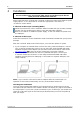
Timebase—A timer that controls the speed at which the scope device captures data.
At slow timebases this process is visible as PicoScope draws the trace across the scope
view from left to right, but at fast timebases PicoScope draws the whole trace in a
single operation. The timebase is measured in units of time (such as seconds) per
division. There are ten divisions across the scope view, so the total time across the
width of the view is ten times the "per division" setting.
USB 1.1. USB (Universal Serial Bus) is a standard port that enables you to connect
external devices to PCs. A typical USB 1.1 port supports a data transfer rate of 12
Mbps (12 megabits per second), much faster than an RS232 port.
USB 2.0. A typical USB 2.0 port supports a data transfer rate that is 40 times faster
than USB 1.1. USB 2.0 is backwards-compatible with USB 1.1.
USB 3.0. A typical USB 3.0 port supports a data transfer rate that is 10 times faster
than USB 2.0. USB 3.0 is backwards-compatible with USB 2.0 and USB 1.