
User manual


PicoScope 3000 A and B Series PC Oscilloscopes and MSOs User's Guide 13
Copyright © 2012 Pico Technology Limited. All rights reserved. ps3000ab.en iss3
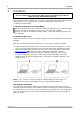
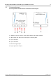
PicoScope 3000 Series 4-channel oscilloscopes
Front
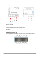
Rear
A. Input channel A
B. Input channel B
C. Input channel C
D. Input channel D
E. External trigger input
F. Signal generator output
1. Probe compensation output
2. LED: red when scope is connected, but not operating. Flashes green when the
oscilloscope is sampling data.
3. DC power socket: for use with the AC adapter supplied. See "Power Options" leaflet
for details.
4. USB 2.0 port: connects to your PC using the Hi-Speed USB cable supplied. See
Installation for powering options.
5. Earth terminal: helps to reduce interference when using a laptop. When using a
laptop computer, the earth terminal can be connected to an external ground point
(for example, on the system you are testing) to provide a ground reference for the
scope. This can help to avoid external noise interfering with your measurements.
8