PicoScope® 3000 Series D and D MSO model oscilloscopes User's Guide ps3000d.en r2 Copyright © 2012–2015 Pico Technology Limited. All rights reserved.
PicoScope 3000D Series Oscilloscope & MSO User's Guide I Contents 1 Introduction ................................................................................................................................ 1 1 Safety information .............................................................................................................................. 3 1 Symbols ..................................................................................................................................
PicoScope 3000D Series Oscilloscope & MSO User's Guide 1 1 Introduction Thank you for buying a PicoScope 3000D Series Oscilloscope from Pico Technology. The PicoScope 3000D Series oscilloscopes are a range of high-specification real-time measuring instruments that connect to the USB port of your computer. With the PicoScope software you can use these devices as oscilloscopes, spectrum analyzers, and arbitrary waveform generators, plus as a logic analyzer on the mixed-signal models.
2 Introduction Some of the benefits provided by the PicoScope 3000D Series oscilloscopes are: Portability. Take the unit with you and simply plug it in to any Windows PC. (Linux and Mac OS X are also supported in the Beta software). Performance. Up to 200 MHz bandwidth, 512 MS buffer, and a 1 GS/s sampling rate. Mixed signal capability. Display analog and digital signals on the same timebase with the MSO models. Flexibility.
PicoScope 3000D Series Oscilloscope & MSO User's Guide 1.1 3 Safety information To prevent possible electrical shock, fire, personal injury, or damage to the product, carefully read this safety information before attempting to install or use the product. In addition, follow all generally accepted safety practices and procedures for working with and near electricity.
4 1.1.1 Introduction Symbols These safety and electrical symbols may appear on the product and throughout this guide. Symbol Description Direct current Alternating current Earth (ground) terminal This terminal can be used to make a measurement ground connection. It is not a safety or protective earth. Chassis terminal Equipment protected throughout by double or reinforced insulation. Possibility of electric shock Caution Appearance on the product indicates a need to read these safety instructions.
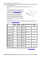
PicoScope 3000D Series Oscilloscope & MSO User's Guide 1.1.2 5 Maximum input ranges Observe all terminal ratings and warnings marked on the product. The table below indicates the full scale measurement range and overvoltage protection range for each oscilloscope model. The full scale measurement ranges are the maximum voltages that can be accurately measured by each instrument. The overvoltage protection ranges are the maximum voltages that can be applied without damaging the oscilloscope.
6 1.1.3 Introduction Grounding WARNING The oscilloscope's ground connection through the USB cable is for measurement purposes only. The oscilloscope does not have a protective safety ground. WARNING Never connect the ground input (chassis) to any electrical power source. To prevent personal injury or death, use a voltmeter to check that there is no significant AC or DC voltage between the oscilloscope ground and the point to which you intend to connect it.
PicoScope 3000D Series Oscilloscope & MSO User's Guide 1.1.5 7 Environment WARNING To prevent injury or death, do not use in wet or damp conditions, or near explosive gas or vapor. CAUTION To prevent damage, always use and store your oscilloscope in appropriate environments. Recommended temperatures and humidity conditions are shown in the table below.
8 Introduction 1.2 Conformance 1.2.1 FCC notice This equipment has been tested and found to comply with the limits for a Class A digital device, pursuant to Part 15 of the FCC Rules. These limits are designed to provide reasonable protection against harmful interference when the equipment is operated in a commercial environment.
PicoScope 3000D Series Oscilloscope & MSO User's Guide 1.3 9 Software license conditions The software supplied with this product is licensed, not sold. Pico Technology Limited grants a license to the person who installs this software, subject to the conditions listed below: Access. The licensee agrees to allow access to this software only to persons who have been informed of these conditions and agree to abide by them. Usage.
10 1.5 Introduction Warranty Pico Technology warrants upon delivery, and for a period of 5 years unless otherwise stated from the date of delivery, that the Goods will be free from defects in material and workmanship.
PicoScope 3000D Series Oscilloscope & MSO User's Guide 2 Product information 2.1 Connector diagrams 11 Standard oscilloscope connectors The analog input channels have standard BNC connectors and standard input impedances. They are therefore compatible with most oscilloscope probes including x10 and switched x1/x10 variants. For optimum performance, always use the probes supplied with your PicoScope.
12 2.1.1 Product information 2-channel model connector diagram PicoScope 3203D, 3204D, 3205D, and 3206D. A. Input channel A B. Input channel B C. Probe compensation pin (above) LED (below) Flashes green when the oscilloscope is sampling data D. External trigger (EXT) input E. Arbitrary waveform generator output F. Earth terminal G. USB port ps3000d.en r2 Copyright © 2012–2015 Pico Technology Limited. All rights reserved.
PicoScope 3000D Series Oscilloscope & MSO User's Guide 2.1.2 13 4-channel model connector diagram PicoScope 3403D, 3404D, 3405D, and 3406D. A. Input channel A B. Input channel B C. Input channel C D. Input channel D E. Probe compensation pin (above) LED (below) Flashes green when the oscilloscope is sampling data F. External trigger (EXT) input G. Arbitrary waveform generator output H. Earth terminal I. USB port J. DC power input Copyright © 2012–2015 Pico Technology Limited. All rights reserved.
14 2.1.3 Product information 2-channel MSO model connector diagram PicoScope 3203D MSO, 3204D MSO, 3205D MSO, and 3206D MSO. A. Input channel A B. Input channel B C. Probe compensation pin (above) LED (below) Flashes green when the oscilloscope is sampling data D. Digital inputs D0 to D15 E. Arbitrary waveform generator output F. Earth terminal G. USB port ps3000d.en r2 Copyright © 2012–2015 Pico Technology Limited. All rights reserved.
PicoScope 3000D Series Oscilloscope & MSO User's Guide 2.1.4 15 4-channel MSO model connector diagram PicoScope 3403D MSO, 3404D MSO, 3405D MSO, and 3406D MSO. A. Input channel A B. Input channel B C. Input channel C D. Input channel D E. Probe compensation pin (above) LED (below) Flashes green when the oscilloscope is sampling data F. Digital inputs D0 to D15 G. Arbitrary waveform generator output H. Earth terminal I. USB port J. DC power input Copyright © 2012–2015 Pico Technology Limited.
16 2.1.5 Product information Digital inputs on MSO models The digital input pins of the 20-pin IDC header plug are shown below. The diagram is drawn as you look at the front panel of the oscilloscope. To avoid crosstalk on the digital inputs when probing signals with very fast edges, always take extra care to: · · · ps3000d.en r2 Keep leads carrying fast signals separate from other input leads. Keep leads carrying fast signals as close as possible to the ground leads.
PicoScope 3000D Series Oscilloscope & MSO User's Guide 2.2 17 Connectivity, power and installation 1. PicoScope software installation Before setting up your PicoScope 3000 Series oscilloscope, it is recommended that you first install the PicoScope 6 software by following the instructions in the supplied Quick Start Guide. There are different connectivity and power supply options for each oscilloscope model depending on its specifications. 2.
18 Product information 3. Oscilloscope installation Once you have connected your oscilloscope to a PC using the appropriate USB cable, Windows will install the device. You will see different alerts depending on your operating system. There is no need to reinsert the software CD. · Windows XP A New Hardware Found wizard will be displayed. Simply click Next to run through the installation. If a Windows Logo Testing warning is displayed, click Continue Anyway.
PicoScope 3000D Series Oscilloscope & MSO User's Guide 2.3 19 Minimum system requirements To ensure that your PicoScope 3000 Series oscilloscope operates correctly, you must have a computer with the system requirements and one of the operating systems shown in the table below. The performance of the oscilloscope will be better with a more powerful PC, and will greatly benefit from a multi-core processor. Item Operating system Specification Windows 7, Windows 8 (not Windows RT), Windows 10*.
20 2.4 Product information Pack contents All PicoScope 3000 Series oscilloscope kits contain: · · · · PicoScope 3000 Series oscilloscope Quick Start Guide Software and reference CD USB 3.0 cable* Each model is also supplied with probes and additional items as shown below. Probes (x1/x10, 1.
PicoScope 3000D Series Oscilloscope & MSO User's Guide 2.5 21 Compensating probes We recommend that you compensate each oscilloscope probe before using it with your PicoScope, and repeat the procedure before using the probes for any precise measurement applications. Specific compensation instructions and all required compensation accessories are supplied with each probe kit. Connecting a probe for compensation 1. Plug the probe's BNC connector into an input channel on the oscilloscope. 2.
22 3 Glossary Glossary API. Application Programming Interface. A set of function calls that give programmers access to the PicoScope 3000 Series (A API) driver. AWG. Arbitrary waveform generator. A signal generator that can play back a waveform of any shape defined by the user. Bandwidth. The range of input frequencies over which the measured signal amplitude is no more than 3 decibels below its true value. Buffer size. The size of the oscilloscope buffer memory, measured in samples.
PicoScope 3000D Series Oscilloscope & MSO User's Guide 23 USB. Universal serial bus. A standard port that enables you to connect external devices to a computer. USB 1.1. An early version of the USB standard, found on some older PCs. PicoScopes will operate slowly using a USB 1.1 port; performance will be greatly improved by using the recommended USB 2.0 or 3.0 port. USB 2.0. A USB 2.0 port uses signaling speeds of up to 480 megabits per second and is backwards-compatible with USB 1.1. USB 3.0. A USB 3.
PicoScope 3000D Series Oscilloscope & MSO User's Guide Index Power adaptor 6, 20 Probe compensation pin Probes 20 compensating A Arbitrary waveform generator (Gen) 15 12, 13, 14, C CE notice Cleaning 25 13, 14, 15 21 R Repair 7 S 8 Safety symbols 7 Servicing 4 7 Software and reference CD System requirements 19 D DC power 13, 15 Digital inputs 14, 15, 16 T Temperature E Trademarks Earth terminal 12, 13, 14, 15 EXT connector 12, 13 External trigger 9 USB cable 20 USB port 12, 13,
United Kingdom headquarters United States headquarters Pico Technology James House Colmworth Business Park St. Neots Cambridgeshire PE19 8YP United Kingdom Pico Technology 320 N Glenwood Blvd Tyler Texas 75702 United States Tel: +44 (0) 1480 396 395 Fax: +44 (0) 1480 396 296 Tel: +1 800 591 2796 Fax: +1 620 272 0981 sales@picotech.com support@picotech.com www.picotech.com ps3000d.en r2 2015-12-04 Copyright © 2012–2015 Pico Technology Limited. All rights reserved.