
User manual

PicoScope 3000D Series Oscilloscope & MSO User's Guide 13
Copyright © 2012–2015 Pico Technology Limited. All rights reserved. ps3000d.en r2
2.1.2
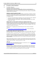
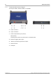
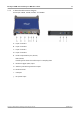
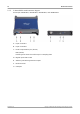
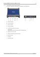
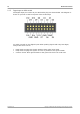
4-channel model connector diagram
PicoScope 3403D, 3404D, 3405D, and 3406D.
A. Input channel A
B. Input channel B
C. Input channel C
D. Input channel D
E. Probe compensation pin (above)
LED (below)
Flashes green when the oscilloscope is sampling data
F. External trigger (EXT) input
G. Arbitrary waveform generator output
H. Earth terminal
I. USB port
J. DC power input