PSEN cs1.
Preface This document is a translation of the original document. All rights to this documentation are reserved by Pilz GmbH & Co. KG. Copies may be made for internal purposes. Suggestions and comments for improving this documentation will be gratefully received. Pilz®, PIT®, PMI®, PNOZ®, Primo®, PSEN®, PSS®, PVIS®, SafetyBUS p®, SafetyEYE®, SafetyNET p®, the spirit of safety® are registered and protected trademarks of Pilz GmbH & Co. KG in some countries.
Contents Introduction Validity of documentation Using the documentation Definition of symbols 4 4 4 4 Safety Intended use Safety regulations Safety assessment Use of qualified personnel Warranty and liability Disposal For your safety 5 5 6 6 6 6 6 7 Unit features 7 Function description Block diagram Operating distances Lateral and vertical offset 7 8 8 9 Wiring Pin assignment, connector and cable 9 10 Connection to evaluation devices 11 Teaching in the actuator 14 Installation 14 Adjustment
PSEN cs1.1p Introduction Validity of documentation This documentation is valid for the product PSEN cs1.1p. It is valid until new documentation is published. This operating manual explains the function and operation, describes the installation and provides guidelines on how to connect the product. Using the documentation This document is intended for instruction. Only install and commission the product if you have read and understood this document. The document should be retained for future reference.
PSEN cs1.1p INFORMATION This gives advice on applications and provides information on special features. Safety Intended use Safety function of safety switch: } 2 safety outputs, each of which supply a high signal when the actuator is in the safety switch's response range and when there is a high signal at the safety inputs. The safety switch meets the requirements in accordance with: } EN 60947-5-3 with the actuator PSEN cs1.1 : PDDB } EN 62061: SIL CL 3 } EN ISO 13849-1: PL eCat.
PSEN cs1.1p Safety regulations Safety assessment Before using a unit it is necessary to perform a safety assessment in accordance with the Machinery Directive. Functional safety is guaranteed for the product as a single component. However, this does not guarantee the functional safety of the overall plant/machine.
PSEN cs1.1p For your safety WARNING! Loss of safety function due to manipulation of the interlocking device Manipulation of the interlocking device may lead to serious injury and death. – You should prevent any possibility of the interlocking device being manipulated through the use of a spare actuator. – Keep the spare actuator in a safe place and protect it from unauthorised access. – If spare actuators are used, these must be installed as described in Installation [ 14].
PSEN cs1.
PSEN cs1.
PSEN cs1.1p } The inputs and outputs of the safety switch must have a protective separation to voltages over 60 VDC. INFORMATION Only use safety relays with a 24 VDC supply voltage. Safety relays with universal power supply or in AC device versions have internal potential isolation and are not suitable as evaluation devices. CAUTION! Do not connect the signal output to 0 V! If the signal output Y32 is connected to 0 V, the safety switch may be damaged as a result.
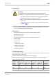
PSEN cs1.1p Connection to evaluation devices Make sure that the selected evaluation device has the following properties: } Dual-channel with feasibility monitoring } OSSD signals are evaluated Connection diagram, single connection Actuator Receiver Evaluation device Operating Manual PSEN cs1.
PSEN cs1.1p Connection diagram, series connection Actuator Receiver Actuator Receiver Actuator Control system Receiver Evaluation device Operating Manual PSEN cs1.
PSEN cs1.1p CAUTION! Extension of delay-on de-energisation When several (n) devices are connected in series, the delay-on de-energisation time adds with the number of interconnected safety switches. The may. delay-on de-energisation is composed of max. delay-on de-energisation actuator + (n-1) x max.
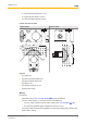
PSEN cs1.1p PNOZmulti 0V PSENcode 24 V PNOZmulti A1 2 A1 A2 7 A2 8 n.c. 6 S11 I0 grün I1 gelb I2 grau 1 S21 3 12 4 22 5 Y32 Legend: I0 Input OSSD I1 Input OSSD I2 Signal input Teaching in the actuator Any Pilz actuator PSEN cs1.1) is detected as soon as it is brought into the response range. Installation CAUTION! The unit's properties may be affected if installed in an environment containing electrically or magnetically conductive material.
PSEN cs1.1p Procedure: Fig.: Sensing faces on the sensor 1. Drill holes (for M5 screws) in the mounting surface to secure the actuator and sensor (see Dimensions in mm [ 17]). 2. Use a screw to fix the sensor to the mounting surface. Make sure that the sensor marking that is be used for operation can be operated using the actuator from the right side. 3. Do not fully tighten the second screw on the safety switch. 4. Use a screw to fix the actuator to the mounting surface.
PSEN cs1.1p Status indicators: } "Power / Fault" LED illuminates green: The unit is ready for operation } "Safety Gate" LED lights up yellow: Actuator is within the response range } "Input" LED lights up yellow: There is a high signal at both inputs Error display through periodic flashing: } "Input" LED lights up yellow: The signal switches from high to low at one input, while a high signal remains on the other input (partial operation). Remedy: Open both channels of the input circuit.
PSEN cs1.1p Table of error codes Error code Decimal Number of flashes Description Remedy 1.4.1 3x short – 1x long – 4x long – 1x long – 3x short Wiring error Rectify wiring error 1.12 3x short – 1x long – 12x long – 3x short Wiring error Rectify wiring error 1.
PSEN cs1.1p Technical details General Approvals Sensor's mode of operation Coding level in accordance with EN ISO 14119 Design in accordance with EN ISO 14119 Classification in accordance with EN 60947-5-3 Pilz coding type Electrical data Supply voltage Voltage Kind Voltage tolerance Output of external power supply (DC) Max. inrush current at UB Max. switching frequency Max.
PSEN cs1.1p Times Delay-on de-energisation Inputs typ. Inputs max. Actuator typ. Actuator max. Risk time in accordance with EN 60947-5-3 Supply interruption before de-energisation Simultaneity, channel 1 and 2 max.
PSEN cs1.1p Mechanical data Sensor flush installation in accordance with EN 60947-5-2 Connection type Material Top Max. torque setting for fixing screws Dimensions Height Width Depth Actuator dimensions Height Width Depth Weight of safety switch Weight of actuator Weight Yes, follow installation guidelines M12, 8-pin male connector PBT 1 Nm 75 mm 40 mm 40 mm 11 mm 40 mm 40 mm 130 g 20 g 150 g Where standards are undated, the 2014-10 latest editions shall apply.
PSEN cs1.1p Supplementary data Radio approval USA/Canada FCC ID: VT8- PSENCS1 IC: 7482A- PSENCS1 FCC/IC-Requirements: This product complies with Part 15 of the FCC Rules and with Industry Canada licence-exempt RSS standards. Operation is subject to the following two conditions: 1) this product may not cause harmful interference, and 2) this product must accept any interference received, including interference that may cause undesired operation.
Technical support is available from Pilz round the clock.