PSEN cs3.
Preface This document is a translation of the original document. All rights to this documentation are reserved by Pilz GmbH & Co. KG. Copies may be made for internal purposes. Suggestions and comments for improving this documentation will be gratefully received. Pilz®, PIT®, PMI®, PNOZ®, Primo®, PSEN®, PSS®, PVIS®, SafetyBUS p®, SafetyEYE®, SafetyNET p®, the spirit of safety® are registered and protected trademarks of Pilz GmbH & Co. KG in some countries.
Contents Introduction Validity of documentation Using the documentation Definition of symbols 4 4 4 4 Safety Intended use Safety regulations Safety assessment Use of qualified personnel Warranty and liability Disposal For your safety 5 5 5 5 6 6 6 7 Unit features 7 Function description Block diagram Operating distances Lateral and vertical offset 7 8 8 9 Wiring Pin assignment, connector and cable 9 10 Connection to evaluation devices 10 Teaching in the actuator 12 Installation Parallel assemb
PSEN cs3.1n Introduction Validity of documentation This documentation is valid for the product PSEN cs3.1n. It is valid until new documentation is published. This operating manual explains the function and operation, describes the installation and provides guidelines on how to connect the product. Using the documentation This document is intended for instruction. Only install and commission the product if you have read and understood this document. The document should be retained for future reference.
PSEN cs3.1n INFORMATION This gives advice on applications and provides information on special features. Safety Intended use Safety function of safety switch: } 2 safety outputs, each of which supply a high signal when the actuator is in the safety switch's response range. The safety switch meets the requirements in accordance with: } EN 60947-5-3 with the actuator PSEN cs3.1 : PDDB } EN 62061: SIL CL 3 } EN ISO 13849-1: PL eCat.
PSEN cs3.1n Functional safety is guaranteed for the product as a single component. However, this does not guarantee the functional safety of the overall plant/machine. In order to achieve the required safety level for the overall plant/machine, define the safety requirements for the plant/machine and then define how these must be implemented from a technical and organisational standpoint.
PSEN cs3.1n For your safety WARNING! Loss of safety function due to manipulation of the interlocking device Manipulation of the interlocking device may lead to serious injury and death. – You should prevent any possibility of the interlocking device being manipulated through the use of a spare actuator. – Keep the spare actuator in a safe place and protect it from unauthorised access. – If spare actuators are used, these must be installed as described in Installation [ 12].
PSEN cs3.1n Block diagram A1 A2 Receiver Actuator Power 12 22 Operating distances On Off Legend: } Sao Assured operating distance: 8 mm } So Typical operating distance: 11 mm } Sr Typical release distance: 14 mm } Sar Assured release distance: 20 mm Operating Manual PSEN cs3.
PSEN cs3.1n Lateral and vertical offset [4] [4] [3] [4] [2] [5] [4] [6] [1] Legend: } [1]: Hysteresis } [2]: Typical operating distance SO } [3]: Typical release distance Sr } [4]: Offset in mm } [5]: Operating distance in mm } [6]: Response range Wiring Please note: } Information given in the "Technical details" must be followed. } The power supply must meet the regulations for extra low voltages with protective separation (SELV, PELV).
PSEN cs3.1n Pin assignment, connector and cable 4 5-pin M12 male connector 3 5 1 2 PIN Pin designation Function Wire colour 1 A1 +24 UB Brown 2 12 Output, channel1 White 3 A2 0 V UB Blue 4 22 Output, channel2 Black 5 - Do not connect Grey The wire colour also applies for the cable available from Pilz as an accessory.
PSEN cs3.1n Connection diagram, single connection Actuator Receiver Evaluation device Suitable Pilz evaluation devices are, for example: } PNOZelog for safety gate monitoring } PNOZpower for safety gate monitoring } PNOZsigma for safety gate monitoring } PNOZ X for safety gate monitoring } PNOZmulti for safety gate monitoring Configure the switch in the PNOZmulti Configurator with switch type 3.
PSEN cs3.1n PNOZ s3 PSENcode 24 V 0V PNOZ s3 A1 1 A1 A2 3 A2 5 Y32 S12 2 12 S22 4 22 PNOZmulti 0V PSENcode 24 V PNOZmulti 3 A2 1 A1 5 n.c. I0 2 12 I1 4 22 Legend: I0 Input OSSD I1 Input OSSD Teaching in the actuator Any Pilz actuator PSEN cs3.1) is detected as soon as it is brought into the response range. Installation CAUTION! The unit's properties may be affected if installed in an environment containing electrically or magnetically conductive material.
PSEN cs3.1n } The actuator should be protected from unauthorised removal and from contamination. Close the mounting holes using the seals provided. The use of seals should be regarded as equivalent to using permanent fastenings in accordance with Clause 7.2c of EN ISO 14119. } Torque setting: Please note the information provided under Technical details [ } The distance between two safety switches must be maintained (see Technical details [ 18]).
PSEN cs3.1n Align the actuator and tighten the screws. [4] [3] [2] [1] For the next steps you will need the seals as illustrated. } (1): Side seal with UL approval } (2): Bottom seal } (3): Top seal, sensing side } (4): Side seal without UL approval Use the seals to close the screws' mounting holes on the actuator } (4): Without UL approval } (1): For UL approval Use the seals (2) to close the unused mounting holes on the actuator.
PSEN cs3.1n Use a screw to fix the safety switch in place. 1. Do not fully tighten the 2nd screw on the safety switch. 2. Attach the screws for the actuator, leaving a distance of 3 … 6 mm between the screw head and plate. [4] [3] [2] [1] For the next steps you will need the seals as illustrated. } (1): Side seal with UL approval } (2): Bottom seal } (3): Top seal, sensing side } (4): Side seal without UL approval Use the seals (2) to close the unused mounting holes on the actuator.
PSEN cs3.1n Use the seals (3) to close the mounting holes on the sensing face of the safety switch. Adjustment } The stated operating distances (see Technical details [ 18]) only apply when the safety switch and actuator are installed facing each other in parallel. Operating distances may deviate if other arrangements are used. } Note the maximum permitted lateral and vertical offset (see Operating distances and Lateral and vertical offset [ 9]).
PSEN cs3.1n Each error code is indicated by three short flashes of the "Input" or "Safety Gate" LED. After a longer pause, the LED will then flash at one second intervals. The number of LED flashes corresponds to a digit in the error code. The error code can consist of up to 3 digits. The digits are separated by a longer period without flashing. The entire sequence is constantly repeated.
PSEN cs3.1n Dimensions in mm 31 160±10 48,5 M12 14,4 ø R 8 4,5 22 37 8 37 22 14,4 4,5 19 18 26,4 18 18 Fig.: Safety switch (left) and actuator (right) Technical details General Approvals Sensor's mode of operation Coding level in accordance with EN ISO 14119 Design in accordance with EN ISO 14119 Classification in accordance with EN 60947-5-3 Pilz coding type Electrical data Supply voltage Voltage Kind Voltage tolerance Output of external power supply (DC) Max.
PSEN cs3.1n Electrical data Max. cable capacitance at the safety outputs No-load, PNOZ with relay contacts PNOZmulti, PNOZelog, PSS Max.
PSEN cs3.1n Environmental data Shock stress In accordance with the standard Acceleration Duration Airgap creepage Overvoltage category Pollution degree Rated insulation voltage Rated impulse withstand voltage Protection type Housing Connector Mechanical data Min. bending radius (for laying) K1 Min.
PSEN cs3.1n Safety characteristic data NOTICE You must comply with the safety-related characteristic data in order to achieve the required safety level for your plant/machine. Operating mode EN ISO 13849-1: 2008 PL 2-ch. OSSD PL e EN ISO 13849-1: 2008 Category Cat.
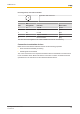
PSEN cs3.1n Order reference Product type Features Connection type Order No. PSEN cs3.1n/PSEN cs3.1 Safety gate system, coded 5-pin M12 male connector 541 003 PSEN cs3.1n (switch) Safety switch, coded 5-pin M12 male connector 541 053 PSEN cs3.1 Actuator, coded 541 080 EC declaration of conformity This product/these products meet the requirements of the directive 2006/42/EC for machinery of the European Parliament and of the Council.
Technical support is available from Pilz round the clock.