PSEN cs3.
Preface This document is a translation of the original document. All rights to this documentation are reserved by Pilz GmbH & Co. KG. Copies may be made for internal purposes. Suggestions and comments for improving this documentation will be gratefully received. Pilz®, PIT®, PMI®, PNOZ®, Primo®, PSEN®, PSS®, PVIS®, SafetyBUS p®, SafetyEYE®, SafetyNET p®, the spirit of safety® are registered and protected trademarks of Pilz GmbH & Co. KG in some countries.
Contents Introduction Validity of documentation Using the documentation Definition of symbols 5 5 5 5 Safety Intended use Safety regulations Safety assessment Use of qualified personnel Warranty and liability Disposal For your safety 6 6 7 7 7 7 7 8 Unit features 8 Function description Block diagram Operating distances Lateral and vertical offset 9 9 10 10 Wiring Pin assignment for cable 11 11 Connection to evaluation devices 12 Teaching in the actuator 15 Installation Parallel assembly Ortho
Contents Order reference 28 EC declaration of conformity 28 Operating Manual PSEN cs3.
PSEN cs3.1p/M12 Introduction Validity of documentation This documentation is valid for the product PSEN cs3.1p/M12. It is valid until new documentation is published. This operating manual explains the function and operation, describes the installation and provides guidelines on how to connect the product. Using the documentation This document is intended for instruction. Only install and commission the product if you have read and understood this document.
PSEN cs3.1p/M12 INFORMATION This gives advice on applications and provides information on special features. Safety Intended use Safety function of safety switch: } 2 safety outputs, each of which supply a high signal when the actuator is in the safety switch's response range and when there is a high signal at the safety inputs. The safety switch meets the requirements in accordance with: } EN 60947-5-3 with the actuator PSEN cs3.1 : PDDB } EN 62061: SIL CL 3 } EN ISO 13849-1: PL eCat.
PSEN cs3.1p/M12 Safety regulations Safety assessment Before using a unit it is necessary to perform a safety assessment in accordance with the Machinery Directive. Functional safety is guaranteed for the product as a single component. However, this does not guarantee the functional safety of the overall plant/machine.
PSEN cs3.1p/M12 For your safety WARNING! Loss of safety function due to manipulation of the interlocking device Manipulation of the interlocking device may lead to serious injury and death. – You should prevent any possibility of the interlocking device being manipulated through the use of a spare actuator. – Keep the spare actuator in a safe place and protect it from unauthorised access. – If spare actuators are used, these must be installed as described in Installation [ 15].
PSEN cs3.1p/M12 Function description The safety outputs may have a high or low signal, depending on the position of the actuator and the signal status of the inputs. In a safe condition there is a low signal at the safety outputs.
PSEN cs3.
PSEN cs3.1p/M12 Wiring Please note: } Information given in the Technical details [ } The max. cable length lmax in the input circuit is calculated from 23] must be followed. – the max. cable capacitance at the safety outputs (see Technical data [ – the minimum permitted supply voltage at the sensor (19.2 V). 23]). } The power supply must meet the regulations for extra low voltages with protective separation (SELV, PELV).
PSEN cs3.1p/M12 Connection to evaluation devices Make sure that the selected evaluation device has the following properties: } Dual-channel with feasibility monitoring } OSSD signals are evaluated Connection diagram, single connection Actuator Receiver Evaluation device Operating Manual PSEN cs3.
PSEN cs3.1p/M12 Connection diagram, series connection Actuator Receiver Actuator Receiver Actuator Control system Receiver Evaluation device Operating Manual PSEN cs3.
PSEN cs3.1p/M12 CAUTION! Extension of delay-on de-energisation When several (n) devices are connected in series, the delay-on de-energisation time adds with the number of interconnected safety switches. The may. delay-on de-energisation is composed of max. delay-on de-energisation actuator + (n-1) x max.
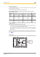
PSEN cs3.1p/M12 PNOZmulti 0V PSENcode 24 V PNOZmulti A1 2 A1 A2 7 A2 8 n.c. 6 S11 I0 grün I1 gelb I2 grau 1 S21 3 12 4 22 5 Y32 Legend: I0 Input OSSD I1 Input OSSD I2 Signal input Teaching in the actuator Any Pilz actuator PSEN cs3.1) is detected as soon as it is brought into the response range. Installation CAUTION! The unit's properties may be affected if installed in an environment containing electrically or magnetically conductive material.
PSEN cs3.1p/M12 Parallel assembly Drill holes (for M4 screws) in the mounting surface to secure the actuator and sensor (see Dimensions [ 21]). Use a screw to fix the safety switch in place. 1. Do not fully tighten the 2nd screw on the safety switch. 2. Attach the screws for the actuator, leaving a distance of 3 … 6 mm between the screw head and plate. Slide the actuator on to the mounting surface. The inscribed area on the actuator (sensing face) should face the safety switch.
PSEN cs3.1p/M12 [4] [3] [2] [1] For the next steps you will need the seals as illustrated. } (1): Side seal with UL approval } (2): Bottom seal } (3): Top seal, sensing side } (4): Side seal without UL approval Use the seals to close the screws' mounting holes on the actuator } (4): Without UL approval } (1): For UL approval Use the seals (2) to close the unused mounting holes on the actuator. Use the seals (3) to close the mounting holes on the sensing face of the safety switch.
PSEN cs3.1p/M12 1. Do not fully tighten the 2nd screw on the safety switch. 2. Attach the screws for the actuator, leaving a distance of 3 … 6 mm between the screw head and plate. [4] [3] [2] [1] For the next steps you will need the seals as illustrated. } (1): Side seal with UL approval } (2): Bottom seal } (3): Top seal, sensing side } (4): Side seal without UL approval Use the seals (2) to close the unused mounting holes on the actuator. Slide the actuator on to the screws.
PSEN cs3.1p/M12 Adjustment } The stated operating distances (see Technical details [ 23]) only apply when the safety switch and actuator are installed facing each other in parallel. Operating distances may deviate if other arrangements are used. } Note the maximum permitted lateral and vertical offset (see Operating distances and Lateral and vertical offset [ 10]). Operation NOTICE The safety function should be checked after initial commissioning and each time the plant/machine is changed.
PSEN cs3.1p/M12 Flash frequency of the "Safety Gate" or "Input" LED I II III IV V Meaning of flash frequency: Flash frequency Meaning I 3 times, short Code for error message II Once, for one second each Code for 1st digit III 4 times, for one second each Code for 2nd digit IV Once, for one second each Code for 3rd digit V 3 times, short Code for error message repeated Table of error codes Error code Decimal Number of flashes Description Remedy 1.4.
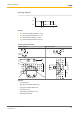
PSEN cs3.1p/M12 Dimensions in mm PSEN cs3.1p 140±10 33 26 M8 14,4 22 4,5 R 8 22 8 37 ø 37 14,4 4,5 19 18 26,4 18 18 Fig.: Safety switch (left) and actuator (right) Operating Manual PSEN cs3.
PSEN cs3.1p/M12 PSEN cs3.1 M12/8-0.15m 31 160±10 48,5 M12 14,4 ø R 8 4,5 22 37 8 37 22 14,4 4,5 19 18 26,4 18 18 Fig.: Safety switch (left) and actuator (right) Operating Manual PSEN cs3.
PSEN cs3.1p/M12 PSEN cs3.1 M12/8-1.
PSEN cs3.1p/M12 Electrical data Supply voltage Voltage Kind Voltage tolerance Output of external power supply (DC) Max. switching frequency Max. cable capacitance at the safety outputs No-load, PNOZ with relay contacts PNOZmulti, PNOZelog, PSS Max. inrush current impulse Current pulse, A1 Pulse duration, A1 No-load current Inputs Number Voltage at inputs Input current range Max.
PSEN cs3.1p/M12 Times Switch-on delay after UB is applied Inputs typ. Inputs max. Actuator typ. Actuator max. Delay-on de-energisation Inputs typ. Inputs max. Actuator typ. Actuator max. Supply interruption before de-energisation Simultaneity, channel 1 and 2 max.
PSEN cs3.1p/M12 Environmental data Protection type Housing Connector Mechanical data Min. bending radius (for laying) K1 Min. bending radius (for constant movement) K1 Cable diameter K1 Actuator 1 Operating distances Assured operating distance Sao Typical operating distance So Assured release distance Sar Typical release distance Sr Repetition accuracy switching distances Change of operating distance with temperature changes Typ. Hysteresis Min.
PSEN cs3.1p/M12 Where standards are undated, the 2014-10 latest editions shall apply. Safety characteristic data NOTICE You must comply with the safety-related characteristic data in order to achieve the required safety level for your plant/machine. Operating mode EN ISO 13849-1: 2008 PL 2-ch. OSSD PL e EN ISO 13849-1: 2008 Category Cat.
PSEN cs3.1p/M12 Order reference Product type Features Connection type Order No. PSEN cs3.1 M12/8-0.15m/ PSEN cs3.1 Safety gate system, coded 8-pin M12 male connector, 0.15 m cable 541 009 PSEN cs3.1p/PSEN cs3.1 Safety gate system, coded 8-pin M8 male connector 541 010 PSEN cs3.1 M12/8-1.5m/ PSEN cs3.1 Safety gate system, coded 8-pin M12 male connector, 1.5 m cable 541 014 PSEN cs3.1 M12/8-0.15m (switch) Safety switch, coded 8-pin M12 male connector, 0.5 m cable 541 059 PSEN cs3.
Technical support is available from Pilz round the clock.