
User Manual Part 1


- 2 -
Blockschaltbild Block diagram Schéma de principe
Funktionsbeschreibung
1154402315
An den Sicherheitsausgängen 12 und 22 liegt
ein High-Signal, wenn gleichzeitig:
der Betätiger im Ansprechbereich ist
(Schutztür geschlossen) und
der Eingang S31 high ist (Steuerbefehl für
magnetische Zuhaltung) und der Zuhaltema-
gnet eingeschaltet ist.
Die Sicherheitsausgänge 12 und 22 sind low,
wenn:
Der Betätiger sich außerhalb des Ansprech-
bereichs befindet oder
der Eingang S31 low ist (Steuerbefehl für ma-
gnetische Zuhaltung) und der Zuhaltemagnet
ausgeschaltet ist
1090038795
Magnetische Zuhaltung und Magnet-
überwachung
Der Zuhaltemagnet wird eingeschaltet, wenn
S31 high ist und der Betätiger erkannt wird
(Schutztür geschlossen).
Die Haltekraft des Zuhaltemagneten wird
beim Einschalten getestet. Wenn dieser Test
erfolgreich abgeschlossen ist, wechseln die
Sicherheitsausgänge in den High-Zustand.
Wird am eingeschalteten Zuhaltemagneten
Windungsunterbruch, oder Windungskurz-
schluss erkannt, wechseln die Sicherheitsaus-
gänge 12 und 22 in den Low-Zustand.
INFO
Wenn die Schutztür im zugehaltenen Zu-
stand gewaltsam geöffnet wird, schalten
die Sicherheitsausgänge ab.
Function description
There is a high signal at safety output 12 and 22
if the following occur simultaneously:
The actuator is within the response range
(safety gate closed) and
Input S31 is high (control command for mag-
netic guard locking) and the locking magnet
is switched on.
Safety outputs 12 and 22 are low if:
The actuator is outside the response range or
Input S31 is low (control command for mag-
netic guard locking) and the locking magnet
is switched off.
Magnetic guard locking device and ma-
gnet monitoring
The locking magnet is switched on if S31 is
high and the actuator is detected (safety gate
closed).
The holding force of the locking magnet is
tested on power-up. If this test is completed
successfully, the safety outputs switch to a
high state.
If an open winding or a winding short circuit is
detected on a locking magnet that is switched
on, safety outputs 12 and 22 switch to a low
state.
INFORMATION
If the safety gate is in a locked condition
and is opened by force, the safety outputs
will shut down.
Description du fonctionnement
Les sorties de sécurité 12 et 22 sont à 1 si, si-
multanément :
l'actionneur est dans la zone de détection
(protecteur mobile fermé) et
l'entrée S31 est à 1 (ordres de commande
avec interverrouillage magnétique) et
l'aimant d'interverrouillage est activé.
Les sorties de sécurité 12 et 22 sont à 0 si :
l'actionneur se trouve à l'extérieur de la zone
de détection ou si
l'entrée S31 est à 0 (ordres de commande
avec interverrouillage magnétique) et
l'aimant d'interverrouillage est désactivé.
Interverrouillage magnétique et surveil-
lance magnétique
L'aimant d'interverrouillage est activé si S31
est à l'état « 1 » et si l'actionneur est détecté
(protecteur mobile fermé).
La force d'interverrouillage de l'aimant est
testée lors de l'activation. Si ce test a été ef-
fectué avec succès, les sorties de sécurité
passent à l'état « 1 ».
Si une coupure de la bobine ou un court-circuit
de la bobine est détecté sur l'aimant d'interver-
rouillage activé, les sorties de sécurité 12 et 22
passent à l'état « 0 ».
INFORMATION
Si le protecteur mobile en position fermée
est ouvert par la force, les sorties de sécu-
rité sont désactivées.
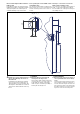
Seiten- und Höhenversatz Lateral and vertical offset Décalage latéral et en hauteur
1209710987
Höhenversatz max. 5 mm
Seitenversatz max. 3 mm
Vertical offset max. 5 mm
Lateral offset max. 3 mm
Décalage en hauteur max. 5 mm
Décalage latéral max. 3 mm
22
Empfänger
Receiver
Récepteur
Betätiger
Actuator
Actionneur
A1
A2
UB
12
Netzteil
Power supply
Alimentation
S31
Magnet
Magnet
Aimant
&
Safety Gate
&
Power / Fault
Lock
Lock
Safety Gate
Power Fault
Input
Seitenversatz/Lateral offset/
Décalage latéral
Höhenversatz/Vertical offset/Décalage vertical