Bosch Sensortec | BME680 Datasheet 1 | 50 BME680 Low power gas, pressure, temperature & humidity sensor BME680 – Datasheet Document revision 1.0 Document release date July 2017 Document number BST-BME680-DS001-00 Technical reference code(s) 1 277 340 511 Notes Data and descriptions in this document are subject to change without notice. Product photos and pictures are for illustration purposes only and may differ from the real product appearance.
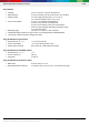
Bosch Sensortec | BME680 Datasheet 2 | 50 BME680 Low power gas, pressure, temperature & humidity sensor The BME680 is a digital 4-in-1 sensor with gas, humidity, pressure and temperature measurement based on proven sensing principles. The sensor module is housed in an extremely compact metal-lid LGA package with a footprint of only 3.0 × 3.0 mm² with a maximum height of 1.00 mm (0.93 ± 0.07 mm).
Bosch Sensortec | BME680 Datasheet 3 | 50 Key features Package Digital interface Supply voltage 3.0 mm x 3.0 mm x 0.93 mm metal lid LGA I²C (up to 3.4 MHz) and SPI (3 and 4 wire, up to 10 MHz) VDD main supply voltage range: 1.71 V to 3.6 V VDDIO interface voltage range: 1.2 V to 3.6 V Current consumption 2.1 µA at 1 Hz humidity and temperature 3.1 µA at 1 Hz pressure and temperature 3.7 µA at 1 Hz humidity, pressure and temperature 0.09‒12 mA for p/h/T/gas depending on operation mode 0.
Bosch Sensortec | BME680 Datasheet 4 | 50 Table of contents 1. Specification 7 1.1 General Electrical Specification ............................................................................................................................ 7 1.2 Gas sensor specification ....................................................................................................................................... 8 1.3 Humidity sensor specification ................................................................
Bosch Sensortec | BME680 Datasheet 5 | 50 5.1 General remarks ................................................................................................................................................. 24 5.2 Memory map ....................................................................................................................................................... 25 5.3 Register description ........................................................................................................
Bosch Sensortec | BME680 Datasheet 6 | 50 7.8.3 Internal package structure ................................................................................................................................ 47 8. Legal disclaimer ............................................................................................................................................48 8.1 Engineering samples ...................................................................................................................
Bosch Sensortec | BME680 Datasheet 7 | 50 1.
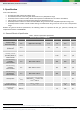
Bosch Sensortec | BME680 Datasheet 8 | 50 1.2 Gas sensor specification Table 2 lists the gas sensor specification. All the parameters are deduced from lab measurements under controlled environmental conditions, which are compliant to the ISO16000-29 standard “Test methods for VOC detectors”. Detailed procedure to measure the gas sensor is available in the Application Note: Measurement Instructions for Lab Environment.
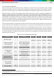
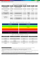
Bosch Sensortec | BME680 Datasheet 9 | 50 Table 3: IAQ system parameter specification3 Parameter Symbol Condition Min Typ Accuracy status4 AXIAQ Android compatible 0 IAQ Resolution IAQrs IAQ Range IAQrg Sensor-to-sensor deviation5 IAQS2S All operation modes ±15% ±15 IAQS2S Sensor-to-sensor deviation ±15% ±15 IAQdrift Drift at low & high concentrations ±1% ±4 Max Unit 3 1 0 Durability to siloxanes6,7,8 500 Table 4: Indoor air quality (IAQ) classification and color-coding9 IAQ I
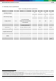
Bosch Sensortec | BME680 Datasheet 10 | 50 1.3 Humidity sensor specification Table 6: Humidity parameter specification Parameter Symbol Condition Operating Range11 Full accuracy range 1 Hz forced mode, temperature and humidity measurement Min Typ Max Unit -40 25 85 °C 0 100 % r.H. 0 65 °C 10 90 % r.H. 2.8 µA 2.1 Supply Current IDD,H Absolute Accuracy AH 20‒80 % r.H., 25 °C, including hysteresis ±3 % r.H. Hysteresis12 HH 10→90→10 % r.H., 25°C ±1.5 % r.H.
Bosch Sensortec | BME680 Datasheet 11 | 50 1.4 Pressure sensor specification Table 7: Pressure parameter specification Parameter Symbol Condition Min Typ Max Operating temperature range TA Operating pressure range operational -40 25 85 full accuracy 0 65 P full accuracy 300 1100 hPa Supply current IDD,LP 1 Hz forced mode, pressure and temperature, lowest power 4.
Bosch Sensortec | BME680 Datasheet 12 | 50 1.5 Temperature sensor specification Table 8: Temperature parameter specification Parameter Symbol Condition Min Typ Max Unit Operating temperature range TA operational -40 25 85 °C IDD,T 1 Hz forced mode, temperature measurement only 1.0 µA AT,25 25 °C ±0.5 °C AT,full 0‒65 °C ±1.0 °C Output resolution RT API output resolution 0.01 °C RMS noise NT Lowest oversampling 0.
Bosch Sensortec | BME680 Datasheet 13 | 50 2. Absolute maximum ratings The absolute maximum ratings are determined over the complete temperature range using corner lots. The values are provided in Table 9. Table 9: Absolute maximum ratings Parameter Condition Min Max Unit Voltage at any supply pin VDD and VDDIO pin -0.3 4.25 V -0.3 VDDIO + 0.3 V -45 +85 °C 0 20 000 hPa HBM, at any pin ±2 kV Machine model ±200 V Voltage at any interface pin Storage temperature ≤ 65% r.H.
Bosch Sensortec | BME680 Datasheet 14 | 50 3. Sensor usage 3.1 Sensor modes The sensor supports low-level power modes: sleep and forced mode. These modes can be selected using the mode<1:0> control register (see Section 5.3.1.3). The key differences between the modes are summarized in Table 10. After a power-up sequence, the sensor automatically starts in sleep mode.
Bosch Sensortec | BME680 Datasheet 15 | 50 3.2 Sensor configuration 3.2.1 Quick start The sensor is configured by writing to a set of control registers (see Chapter 5 for a detailed list of all available registers and their descriptions). This section illustrates, with the help of a basic step-by-step example, how to configure the sensor for simple forced mode measurements with a single heater set-point. For a more detailed description of the measurement flow, please refer to Section 3.3.
Bosch Sensortec | BME680 Datasheet 16 | 50 3.2.2 Sensor configuration flow Picture 2 illustrates which control registers must be set. For details on the individual control registers, please refer to Chapter 5. Moreover, details on the measurement flow for the individual modes can be found in Section 3.3.
Bosch Sensortec | BME680 Datasheet 17 | 50 3.3 Measurement flow Referring to Figure 1, the BME680 measurement period consists of a temperature, pressure and humidity measurement with selectable oversampling. Moreover, it contains a heating phase for the gas sensor hot plate as well as a measurement of the gas sensor resistance. After the measurement period, the pressure and temperature data can be passed through an optional IIR filter, which removes short-term fluctuations.
Bosch Sensortec | BME680 Datasheet 18 | 50 3.3.4 IIR filter The environmental pressure is subject to many short-term changes, caused external disturbances. To suppress disturbances (e.g. slamming of door or wind blowing into the sensor) in the output data without causing additional interface traffic and processor work load, the BME680 features an internal IIR filter (see Section 5.3.2.4).
Bosch Sensortec | BME680 Datasheet 19 | 50 Table 11: Variable names and register addresses for res_heat_x calculation Variable name Register address (LSB / MSB) par_g1 0xED par_g2 0xEB/0xEC par_g3 0xEE res_heat_range 0x02 <5:4> res_heat_val 0x00 For each of the 10 temperature set-points, the heating duration must be specified. Referring to Figure 1, the heating phase starts after the temperature, pressure and humidity measurements are complete.
Bosch Sensortec | BME680 Datasheet 20 | 50 Table 12: List of gas ranges and corresponding constants used for the resistance calculation gas_range Constants (to be integrated in the driver) const_array1 const_array2 0 1 8000000 1 1 4000000 2 1 2000000 3 1 1000000 4 1 499500.4995 5 0.99 248262.1648 6 1 125000 7 0.992 63004.03226 8 1 31281.28128 9 1 15625 10 0.998 7812.5 11 0.995 3906.25 12 1 1953.125 13 0.99 976.5625 14 1 488.28125 15 1 244.
Bosch Sensortec | BME680 Datasheet 21 | 50 4. Software and use cases 4.1 BSEC software BME680 sensor is intended to be used together with Bosch Software Environmental Cluster (BSEC) solution and BME6xy sensor API to unlock its full potential. The BSEC software features intelligent algorithms which enable use cases such as indoor-air-quality monitoring using the BME680.
Bosch Sensortec | BME680 Datasheet 22 | 50 Table 14: BSEC outputs Output Included in solution Description IAQ ALL Raw pressure ✔ ✔ Raw data from sensor API bypassed to BSEC output Raw temperature ✔ ✔ Raw data from sensor API bypassed to BSEC output Raw relative humidity ✔ ✔ Raw data from sensor API bypassed to BSEC output Raw gas resistance ✔ ✔ Raw data from sensor API bypassed to BSEC output Sensor-compensated temperature ✔ ✔ Temperature which is compensated for internal crossinfl
Bosch Sensortec | BME680 Datasheet 23 | 50 4.2 Indoor-air-quality BME680 is a metal oxide-based sensor that detects VOCs by adsorption (and subsequent oxidation/reduction) on its sensitive layer. Thus, BME680 reacts to most volatile compounds polluting indoor air (one exception is for instance CO 2). In contrast to sensors selective for one specific component, BME680 is capable of measuring the sum of VOCs/contaminants in the surrounding air. This enables BME680 to detect e.g.
Bosch Sensortec | BME680 Datasheet 24 | 50 5. Global memory map and register description 5.1 General remarks Communication with the device is performed by reading from and writing to registers. Registers have a width of 8 bits. If I2C is used, 8-bit addressing is utilized. If SPI is used, 7-bit address is only available for register access. For details on the interface, consult Chapter 6. In SPI mode complete memory map is accessed using page 0 and page 1. Register spi_mem_page is used for page selection.
Bosch Sensortec | BME680 Datasheet 25 | 50 5.2 Memory map The memory map is given in Table 16: Memory mapTable 16, noting that not all reserved registers are depicted.
Bosch Sensortec | BME680 Datasheet 26 | 50 5.3 Register description 5.3.1 General control registers 5.3.1.1 SPI 3 wire interrupt enable – spi_3w_int_en Register Name ctrl_hum Address Content 0x72 spi_3w_int_en <6> Description New data interrupt can be enabled if the device is in SPI 3 wire mode and pi_3w_int_en=1. The new data interrupt is then indicated on the SDO pad. 5.3.1.
Bosch Sensortec | BME680 Datasheet 27 | 50 5.3.1.5 Reset – reset Writing 0xB6 to this register initiates a soft-reset procedure, which has the same effect like power-on reset. The default value stored in this register is 0x00. Register Name Address Content Description reset 0x60 (Page 0 in SPI mode) 0xE0 in I2C reset<7:0> Resets the device Address Content Description 0x50(Page 0 in SPI mode) 0xD0 in I2C chip_id<7:0> Chip id of the device 5.3.1.
Bosch Sensortec | BME680 Datasheet 28 | 50 5.3.2.3 Over sampling setting – Pressure data – osrs_p Register Name ctrl_meas Address Content Description 0x74 osrs_p<4:2> Pressure oversampling settings as shown in the following table osrs_p<2:0> Pressure oversampling 000 Skipped (output set to 0x8000) 001 oversampling ×1 010 oversampling ×2 011 oversampling ×4 100 oversampling ×8 101, Others oversampling ×16 5.3.2.
Bosch Sensortec | BME680 Datasheet 29 | 50 5.3.3 Gas control registers The sensor can have 10 programmable gas sensor heater set-points. A set-point consists of a target heater resistance, heater-on time and optionally an initial heater current. 5.3.3.1 Heater current - idac_heat_x BME680 contains a heater control block that will inject enough current into the heater resistance to achieve the requested heater temperature.
Bosch Sensortec | BME680 Datasheet 30 | 50 5.3.3.3 Gas Sensor wait time - gas_wait_x Referring to Figure 1, the time between the beginning of the heat phase and the start of gas sensor resistance conversion depends on gas_wait_x setting as mentioned below. Heater set-point Register name Address Content Description 0...9 gas_wait_x x is from 0 to 9 0x64…0x6D gas_wait_x<5:0> x is from 0 to 9 64 timer values with 1 ms step sizes, all zeros means no wait 0...
Bosch Sensortec | BME680 Datasheet 31 | 50 5.3.3.5 Heater profile selection - nb_conv nb_conv is used to select heater set-points of the sensor. The different heater set-points are described in the sections above.
Bosch Sensortec | BME680 Datasheet 32 | 50 5.3.4 Data registers In this section, the data registers for the temperature, pressure, humidity and gas sensors are explained. Shadowing registers are utilized to buffer the data and to ensure stable data in case an update of the data registers occurs simultaneously with the serial interface reading out. 5.3.4.
Bosch Sensortec | BME680 Datasheet 33 | 50 5.3.5 Status registers 5.3.5.1 New data status The measured data are stored into the output data registers at the end of each TPHG conversion phase along with status flags and index of measurement. Register Name Address Content Description meas_status_0 0x1D new_data_0<7> New data flag 5.3.5.
Bosch Sensortec | BME680 Datasheet 34 | 50 5.3.5.5 Gas valid status In each TPHG sequence contains a gas measurement slot, either a real one which result is used or a dummy one to keep a constant sampling rate and predictable device timing. A real gas conversion (i.e., not a dummy one) is indicated by the gas_valid_r status register. Register Name gas_r_lsb Address 0x2B Content gas_valid_r<5> Description Gas valid bit 5.3.5.
Bosch Sensortec | BME680 Datasheet 35 | 50 6. Digital interfaces The sensor supports the I²C and SPI digital interfaces, where it acts as a slave for both protocols. The I²C interface supports the Standard, Fast and High Speed modes. The SPI interface supports both SPI mode ‘00’ (CPOL = CPHA = ‘0’) and mode ‘11’ (CPOL = CPHA = ‘1’) in 4-wire and 3-wire configuration.
Bosch Sensortec | BME680 Datasheet 36 | 50 The I²C interface uses the following pins: SCK: SDI: SDO: serial clock (SCL) data (SDA) Slave address LSB (GND = ‘0’, VDDIO = ‘1’) CSB must be connected to VDDIO to select I²C interface. SDI is bi-directional with open drain to GND: it must be externally connected to VDDIO via a pull up resistor. Refer to Chapter 7 for connection instructions.
Bosch Sensortec | BME680 Datasheet 37 | 50 6.3 SPI interface The SPI interface is compatible with SPI mode ‘00’ (CPOL = CPHA = ‘0’) and mode ‘11’ (CPOL = CPHA = ‘1’). The automatic selection between mode ‘00’ and ‘11’ is determined by the value of SCK after the CSB falling edge. The SPI interface has two modes, namely 4-wire and 3-wire mode. However, the protocol is the same for both. The 3-wire mode is selected by setting ‘1’ to the register spi3w_en. The pad SDI is used as a data pad in 3-wire mode.
Bosch Sensortec | BME680 Datasheet 38 | 50 6.3.2 SPI read Reading is done by lowering CSB and first sending one control byte. The control bytes consist of the SPI register address (= full register address without bit 7) and the read command (bit 7 = RW = ‘1’). After writing the control byte, data is sent out of the SDO pin (SDI in 3-wire mode); the register address is automatically incremented. The SPI read protocol is depicted in Picture 8.
Bosch Sensortec | BME680 Datasheet 39 | 50 6.4.2 I²C timings For I²C timings, the following abbreviations are used: “S&F mode” = standard and fast mode “HS mode” = high speed mode Cb = bus capacitance on SDA line All other naming refers to I²C specification 2.1 (January 2000). The I²C timing diagram is in Picture 9.
Bosch Sensortec | BME680 Datasheet 40 | 50 6.4.3 SPI timings The SPI timing diagram is in Picture 10, while the corresponding values are given in Table 19. All timings apply both to 4and 3-wire SPI.
Bosch Sensortec | BME680 Datasheet 41 | 50 7. Pin-out and connection diagram 7.1 Pin-out The pin numbering of BME680 is performed in the untypical clockwise direction when seen in top view and counter-clockwise when seen in bottom view. Picture 11 and Table 20 give a detailed description and illustration of the input/output pins.
Bosch Sensortec | BME680 Datasheet 42 | 50 7.2 Connection diagrams For the I2C connection, it is recommended to use 100 nF for C1 and C2. Moreover, the value for the pull-up resistors R1 and R2 should be based on the interface timing and the bus load; a normal value is 4.7 kΩ. Finally, a direct connection between CSB and VDDIO is required. Similarly for the 4- and 3-wire SPI connections, it is suggested to use 100 nF for C 1 and C2.
Bosch Sensortec | BME680 Datasheet 43 | 50 7.3 Package dimensions Picture 13: Package dimensions for top, bottom and side view Modifications reserved |Data subject not change without notice | Printed in Germany Document number: BST-BME680-DS001-00 Revision_1.
Bosch Sensortec | BME680 Datasheet 44 | 50 7.4 Landing pattern recommendation For the design of the landing pattern, the dimensions shown in Picture 14: Recommended landing pattern (top view; dimensions are in milli-meters) are recommended. It is important to note that areas marked in red are exposed PCB metal pads. In case of a solder mask defined (SMD) PCB process, the land dimensions should be defined by solder mask openings. The underlying metal pads are larger than these openings.
Bosch Sensortec | BME680 Datasheet 45 | 50 7.5 Marking 7.5.1 Mass production devices Table 21: Marking of mass production parts Marking Symbol Description CCC Lot counter: 3 alphanumeric digits, variable to generate mass production trace-code T Product number: 1 alphanumeric digit, fixed to identify product type, T = “S” “S” is associated with the product BME680 (part number 1 277 340 511) L Sub-contractor ID: 1 alphanumeric digit, variable to identify sub-contractor (L = “P”) 7.5.
Bosch Sensortec | BME680 Datasheet 46 | 50 7.
Bosch Sensortec | BME680 Datasheet 47 | 50 7.8 Environmental safety 7.8.1 RoHS The BME680 sensor meets the requirements of the EC restriction of hazardous substances (RoHS) directive, see also: Directive 2011/65/EU of the European Parliament and of the Council of 8 June 2011 on the restriction of the use of certain hazardous substances in electrical and electronic equipment. 7.8.2 Halogen content The BME680 is halogen-free.
Bosch Sensortec | BME680 Datasheet 48 | 50 8. Legal disclaimer 8.1 Engineering samples Engineering Samples are marked with an asterisk (*) or (e) or (E). Samples may vary from the valid technical specifications of the product series contained in this data sheet. They are therefore not intended or fit for resale to third parties or for use in end products. Their sole purpose is internal client testing. The testing of an engineering sample may in no way replace the testing of a product series.
Bosch Sensortec | BME680 Datasheet 49 | 50 9. Document history and modifications Rev. 1.0 Chapter Description of modifications Date Initial release July 2017 Modifications reserved |Data subject not change without notice | Printed in Germany Document number: BST-BME680-DS001-00 Revision_1.
Bosch Sensortec | BME680 Datasheet 50 | 50 Bosch Sensortec GmbH Gerhard-Kindler-Straße 9 72770 Reutlingen / Germany www.bosch-sensortec.com Modifications reserved | Printed in Germany Preliminary - specifications subject to change without notice Document number: BST-BME680-DS001-00 Revision_1.0_072017 Modifications reserved |Data subject not change without notice | Printed in Germany Document number: BST-BME680-DS001-00 Revision_1.