
Technical Manual


PINEAPPLE TECHNOLOGY, INC.
UTX5KW-A Operating and Service Manual
D. ADP500 & PAS10 PERFORMANCE MONITOR
The ADP500 & PAS10 (PERFORMANCE MONITOR) provides the following functions:
1. Monitors FORWARD AND REFLECTED POWER to the antenna and presents it as a percentage of
power rating. The transmitter comes set to 100% P-Sync power based on the ratings of the transmitter
or service requirements.
2. Monitors Aural Power as a percentage of P-Sync rating (5-10% typical)
3. Provides a HIGH ANTENNA VSWR MONITOR In the event of an antenna or coax failure where
the reected power exceeds 25% the transmitter will shutdown. Front panel LED will change from
green to red in case of a fault.
4. Provides current monitoring of all the pallets used in the ten (10) U600LDV-2 power amplier
assemblies. The current levels can be read directly from the multi-meter on the front panel. Individual
pallets are selectable on the ADP500, and the PA assemblies are selected using the PAS10. In normal
operations, a PA FAULT is indicated by going from green to red. RED indicates that the current level
is below 500 ma and a transistor could have failed. To read the actual current, select the appropriate PA
Bank using the PAS10. The ADP500 will now display status of each pallet in that PA. The multi-meter
will read the actual current.
5. A PA INHIBIT switch is provided for failure diagnostic purposes. When activated, this switch allows
the technician to monitor the bias currents for each pallet. These readings should be recorded when
the transmitter is rst installed and used as a reference. This is the best way to trouble shoot possible
transistor problems. When in the PA INHIBIT mode, the RF PWR OFF LED will change from green
to red indicating that the “SHUTDOWN LINE” Is at a TTL 0 state and the output power has been
reduced to near zero.
6. An RF MONITOR port (BNC) is available to connect a spectrum analyzer for monitoring the output
signal.
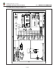
METER SELECTOR SWITCHES
The PAS10 is used to select the appropriate PA Module ( U600LDV-2) for performance display on the
ADP500. PA designations are PA1 starting from the top row going left to right with PA10 being on the
right side in the fth (5th) row down when viewed from the front of the transmitter.
The Rotor Switch on the ADP500 is the detail selector for the multi-meter. The various positions are
dened as follows:
PA1 THRU PA5 ................................................... Reads PA pallet currents as selected
Typical reading in INHIBIT MODE 1.5 TO 2.2 A
Typical reading with SMTPE BARS — 5-7 A for PA1
thru PA4 Typical reading with SMTPE BARS — 2-3 A
for PA5
PA6 ..................................................................... NO CONNECTION
PS VOLTS............................................................ Reads DC Voltage applied to PA Stages
Typical reading would be +29 to 32 VDC
P FWRD .............................................................. Reads PA output power in P-Sync percentage of rating.
Full power reading would be 100%
V — THEORY OF OPERATION
Page 9