MediaStream Media Gateway Version 2.50 Installation, Setup, and Operations Guide Pinnacle® Systems, Inc. 280 N. Bernardo Avenue Mountain View, CA 94043 June, 2005 P/N 37T100105 REV.
Trademarks All brand or product names mentioned herein are used for identification purposes only and may be trademarks or registered trademarks of their respective companies. Copyright © 2005 Pinnacle Systems, Inc. All Rights Reserved. Reproduction, adaptation, or translation of this document without prior written permission is prohibited, except as allowed under copyright laws. Printed in the United States. Note: The information in this document is subject to change without notice or obligation.
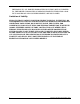
Official Notices and Warranties Software License Agreement IMPORTANT—READ CAREFULLY: This Software License Agreement is a legal agreement between You and Pinnacle (or its suppliers). This System contains certain Pinnacle computer software (“Software”), associated media, printed materials, and electronic documentation. By using the Software, You agree to be bound by the terms of this Software License Agreement.
THE PRODUCTS. ALL IMPLIED WARRANTIES, INCLUDING, BUT NOT LIMITED TO, THE IMPLIED WARRANTIES OF MERCHANTABILITY, FITNESS FOR A PARTICULAR PURPOSE AND NONINFRINGEMENT, ARE DISCLAIMED.
Table of Contents CHAPTER 1: INTRODUCTION . . . . . . . . . . . . . . . . . . . . . . . . . . . . . . . . . . . . . . . . . . . . . . . . . . . . 7 System Overview . . . . . . . . . . . . . . . . . . . . . . . . . . . . . . . . . . . . . . . . . . . . . . . . . . . . . . . . . . . . 7 MediaStream Media Gateway Application. . . . . . . . . . . . . . . . . . . . . . . . . . . . . . . . . . . . . . . . . . . . . . 7 ConnectPlus 1000 Gateway Computer . . . . . . . . . . . . . . . . . . . . . . . . . . . . . . .
Contents XSend a sequence with HD422 . . . . . . . . . . . . . . . . . . . . . . . . . . . . . . . . . . . . . . . . . . . . . . . . . . . 45 CHAPTER 4: WORKFLOW AND FILE TRANSFER . . . . . . . . . . . . . . . . . . . . . . . . . . . . . . . . . . . . 47 Using the MMG Client . . . . . . . . . . . . . . . . . . . . . . . . . . . . . . . . . . . . . . . . . . . . . . . . . . . . . . . . . . . . 47 Transferring a File . . . . . . . . . . . . . . . . . . . . . . . . . . . . . . . . . . . . . . . . . . . . .
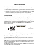
Chapter 1: Introduction Pinnacle System’s MediaStream Media Gateway (MMG) solution provides the following common production workflows: • Partial and full file copy from the SAN to a Liquid blue workstation and importing into Liquid blue for editing while still actively transferring. • File transfer from a Liquid blue workstation to the SAN, where the file is played by a Media Stream Server. A finished sequence can be fused to a file in a designated directory.
Chapter 1: Introduction ConnectPlus 1000 Gateway Computer The ConnectPlus 1000 gateway consists of a computer with an Intel processor that runs the Microsoft Windows OS. It also includes a Fibre Channel card for connection to the storage arrays via the Fibre Channel switches. This gateway connects the Liquid blue workstation with the MediaStream Networked Storage Systems and the MSS 8000 NS server.
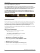
Chapter 1: Introduction About This Guide This Guide provides instructions for installing and configuring product-specific components of the Pinnacle Systems MediaStream Media Gateway. For instructions on setting up and configuring your MediaStream network and the ConnectPlus 1000 gateway, connecting your Liquid blue workstation components, and installing and working with Palladium Exchange, see the specific documentation for these components that is included with your system.
Chapter 1: Introduction 10 MMG Installation, Setup, and Operations Guide
Chapter 2: System Connections This chapter describes the connections for the Liquid blue workstation and the ConnectPlus 1000 gateway, which are connected to a networked storage system with one or more MSS 8000 NS servers. For instructions on connecting your networked storage system, see your Liquid Reference Manual and the MSS 8000 NS Installation and Site Guide.
Chapter 2: System Connections Figure 2-2 shows the connections between the Liquid blue workstation and other system components. Audio/Video Monitor FireWire RS-422/1394 DV Tape I/O VGA Monitor PC Liquid blue Box .
Chapter 2: System Connections • Attach the parallel type of dongle to the parallel port in the back of the Liquid blue client computer as shown in Figure 2-4. Tighten the thumbscrews on the parallel port dongle to ensure that it is attached securely. Dongle attached to parallel port Figure 2-4: Liquid Dongle Parallel Port Placement Liquid Client Computer to LAN/WAN Cable: Gb RJ-45 cable Connection: The Liquid client computer’s on-board Gb Ethernet port to your network.
Chapter 2: System Connections Figure 2-5 shows the GNIC (Gb Ethernet) port on the Liquid client computer that connects to your network. Liquid Workstation Rear Panel (enlarged) GNIC Port Figure 2-5: Liquid blue Workstation’s GNIC Port ConnectPlus 1000 Gateway Connections A Gigabit Ethernet port provides the LAN/WAN connection to your network.
Chapter 3: Installation and Setup The Liquid blue application and the MediaStream Media Gateway client application are installed on the Liquid blue workstation. The MediaStream Media Gateway server application is installed on the ConnectPlus 1000 gateway(s). Install Liquid blue This section covers the installation of Liquid blue v6.10 build 4190. Installation of Liquid Blue Service Pack 2 build 4312 is also covered. Begin the Installation To install Liquid blue: 1. Insert the Liquid blue version 6.
Chapter 3: Installation and Setup 9. A progress bar shows the percentage of the installation completed. Figure 3-2: Installation Progress Bar 10. Enter your serial number as shown in Figure 3-3. The Serial number is located on the Blue installation CD sleeve. If you can not locate your serial number, call Pinnacle technical support. Figure 3-3: Serial Number Dialog 11. After Liquid blue is installed, files are extracted for the TitleDeko setup.
Chapter 3: Installation and Setup 15. When finished, the Install Wizard Complete window is displayed. Click Finish. 16. When the Installation Completed! window is displayed, the Liquid blue application has been successfully installed. Click Finish to leave the installer. Figure 3-5: Liquid blue Installation Completed Screen 17. Before using Liquid blue, you need to install the service packs. Insert the MMG program CD and find the directory Liquid V6.10SP2. 18. Run the application liquid.XML.Setup.
Chapter 3: Installation and Setup Installing the MMG Client The MMG Client is installed on the Liquid blue workstation or PS100 server (if applicable). Note: For PS100 systems, the MMG client should be installed on the PS100 system and all of the Blue clients. The MMG Client installer modifies masfilter.ini on Blue clients. If the MASFilter is re-installed, the MMG Client should be re-installed, or masfilter.ini should be edited; “audioenc.exe;” should be added to the string after “applist=” in masfilter.
Chapter 3: Installation and Setup 5. Select the destination folder for the installed application or accept the default location. Click Next. 6. In the Startup Settings window (Figure 3-8), accept all of the default values. Figure 3-8: Server Setup Window 7. Click Install to start the installation. A progress bar shows the percentage of the installation completed. Figure 3-9: Installation Status Window 8. After the installation is complete, the InstallShield Wizard Complete window is displayed.
Chapter 3: Installation and Setup Configure the FileZilla (FTP) server connection 1. In the Connect to Server dialog box, accept the default values given for the local host IP address (127.0.0.1) and the port (14147) for administrative connections. No password is required. 2. The FileZilla server window is displayed (Figure 3-10). Figure 3-10: FileZilla Window To change the user and password: 1.
Chapter 3: Installation and Setup 2. Highlight the user you want to change, root in Figure 3-11, and click the rename button. Type the new name in the edit box and click OK. Delete all of the dots in the password box and type a new password. Click OK. To change the home directory: 1. From the FileZilla window, click edit >users and the users configuration window appears: Figure 3-12: User Edit Dialog 2. Click on Shared Folders: Figure 3-13: Shared Folders 3.
Chapter 3: Installation and Setup FileZilla configuration for a PS100: Because the PS100 uses shared storage, a separate watch folder and login should be used for each Blue client to ensure correct autoimport functionality. Speed limits should also be set to ensure the PS100 has ample bandwidth for real-time operations. Create a folder on the PS100 V drive for each Blue client, i.e. V:\Blue1, V:\Blue2 etc. Perform the following steps on the PS100. To configure users: 1.
Chapter 3: Installation and Setup 3. Click on the shared folders tab. Figure 3-15: Shared Folders 4. Highlight the user added in step 4 above. In the shared folder group box, click the add button. Navigate to the folder designated for that user and click OK. Check all 8 checkboxes in the Shared Folders group box and click the Set as home dir button. 5. Repeat steps 2-4 for each Blue client connected to the PS100. Configure Speed Limits 1. From the FileZilla window, click edit >Settings.
Chapter 3: Installation and Setup Note: This number may change depending on the number of clients connected to the PS100, and the client’s bandwidth allocation. The total MAS bandwidth allocation (-lb on the MAS command line) should be adjusted to compensate for the reserved bandwidth given to FileZilla. Configure the MMG The MMG needs the network information of the TCS server, the source host(s), and the destination host(s). The IP addresses of these machines must be entered for MMG to function.
Chapter 3: Installation and Setup 3. Click the Add TCS button. Figure 3-18: Add TCS server 4. The label shows in the dropdown list. Figure 3-19: Choose Server To add a host to the MMG, edit the fields of the lower group box labeled Edit Hosts: 1. Enter the IP address of the host. 2. Choose the port to be used. ConnectPlus gateways use port 21, all other hosts use port 2119. 3. Enter a label for the host. This can be the hostname, or any unique label to identify the machine.
Chapter 3: Installation and Setup 6. Click the Add Host button. Figure 3-20: Add Host 7. The host appears in the dropdown menu. To delete TCS servers, or hosts: 1. Choose the TCS or host from the dropdown menu. 2. Click the delete button. A confirmation dialog appears, click Yes to delete. To edit TCS servers or hosts: 1. Choose the TCS or host from the dropdown menu. 2. Edit the field(s) you wish to change. 3. Click the save button. A confirmation dialog appears, click Yes to overwrite.
Chapter 3: Installation and Setup Installing the MMG Server on the Gateway To install the MMG server on the gateway: 1. Insert the MMG installation disk into the gateway computer’s CD drive. Locate the MMGServer.exe and double-click it to start the installation. 2. After the Welcome window is displayed, click Next to continue with the installation. 3. The Ready to Install window is displayed. Click Install to begin the installation.
Chapter 3: Installation and Setup 9. The Ready to Install window is displayed. Click Install. 10. A progress bar shows the installation status. 11. The Completing the Setup window is displayed. Click Finish. 12. After the MMG server has been installed, the InstallShield Wizard Complete window is displayed. Choose Yes to restart the PC and click Finish.
Chapter 3: Installation and Setup Liquid Blue Setup Setting Up a Timeline in Blue When importing media from MSS, it is important to set the timecode format on blue to match the original media. For NTSC, there is a drop frame format, and a non-drop frame format. For PAL, there is only one timecode format and it does not require any changes. The default setting on Blue is non-dropframe. To setup a dropframe timeline, click the create new timeline icon.
Chapter 3: Installation and Setup Editing While Transfer Extracting audio from a clip lets you edit the clip on the Liquid blue station during transfer from the MSS to Liquid. Using XReceive automatically extracts audio and trust metadata. The following describes the settings for a manual file import into blue. You can access the file through the Import Media dialog box in Liquid blue.
Chapter 3: Installation and Setup Audio Settings For Blue MediaStream has the capability to use up to eight tracks, or four pair of audio tracks. Liquid Blue natively uses two pair of audio tracks, but can be set up to use eight. When a timeline with eight tracks of audio is XSent to MSS, all eight are available on MSS. The audio output in Blue is controlled by logical busses. Each logical bus produces one pair of audio output files. To generate four pairs of audio tracks, configure four logical busses.
Chapter 3: Installation and Setup Notice that all of the columns show Stereo as the logical bus. To create an additional logical output bus, click on the text “Stereo”, choose add new logical output bus, and choose Stereo (Figure 3-28). Figure 3-28: Stereo Setting The column now shows Stereo(2). Repeat these steps until you have the number of audio pairs desired. Figure 3-29 shows an audio setup with four logical busses configured.
Chapter 3: Installation and Setup Figure 3-30 shows the output mapping for four pairs of audio. Figure 3-30: Output Mapping When you are finished, click the exit icon to exit the audio tool.
Chapter 3: Installation and Setup Setting up Blue Codecs The following section describes how to set up various codecs and formats in blue. The description includes configurations needed during the XSend workflow. For more information on the XSend workflow, see Using XSend on page 58. 1. To setup a codec, go to Edit menu > Control Panel and select Site Tab. 2. Double click Codec Presets.
Chapter 3: Installation and Setup Preset 1: SD PS 420 IBBP 1. Select the “MPEG-2 MP@HL (M2V)” codec as starting point. Click the two plus symbols on the right to duplicate this preset. Figure 3-32: Codec Presets 2. Type a descriptive name for the preset you want to create in the textfield.For this example enter SD PS 422 IBBP. 3. To edit the Codec Properties click the top Edit button. In Codec Properties select a maximum Bitrate of 25 MBit/s. Keep the “I-Frame only” and the “4:2:2” checkbox unchecked.
Chapter 3: Installation and Setup In the Render/Fuse Codec Pres. dropdown list box, select the Codec Preset value you just created. For this example we select the Preset 1: SD PS 420 IBBP Figure 3-35: Timeline Properties XSend a sequence with 420 1. To XSend a sequence, right-click the sequence and select XSendTo. From the submenu that appears, select XSendToMSS.
Chapter 3: Installation and Setup 2. When the XSend To XSend To MSS dialog appears, leave the default settings and click OK. Figure 3-37: XSend to XSend to MSS dialog 3. The IBP Settings dialog appears.Select the Reference Set. Change the Bitrate mode to Constant (CBR). Drag Maximum Bit Rate slider to 15.00. Its ok to leave the other settings as default. Click the checkbox to accept settings.
Chapter 3: Installation and Setup 4. Click OK in the Fuse Sequence dialog that appears. As the fuse begins, your screen should look something like this (Figure 3-39): Figure 3-39: Fuse Sequence Progress Preset 2: SD PS S422 IBBP and SD PS E422 IBBP 1. To setup a codec, go to Edit menu > Control Panel and select Site Tab. 2. Double click Codec Presets. 3. Select the “MPEG-2 MP@HL (M2V)” codec as starting point.
Chapter 3: Installation and Setup Setup the Codec Preset 2 in the timeline To setup a Codec Preset right click a empty space of the timeline and select Timeline properties... from the drop-down menu (see Figure 3-34 on page 35). In the Render/Fuse Codec Pres. dropdown list box, select the Codec Preset value you just created. For this example we select the Preset 2: SD PS 422 IBBP. Figure 3-41: Preset 2 Codec Settings XSend a sequence with Standard 422 (s422) 1.
Chapter 3: Installation and Setup Preset 3: SD MXF S422 I-Frame only and SD MXF E422 I-Frame only 1. To setup a codec, go to Edit menu > Control Panel and select Site Tab. 2. Double click Codec Presets. 3. Select the “MPEG-2 MP@HL (M2V)” codec as starting point. Click the two plus symbols on the right to duplicate this preset (see Figure 3-32 on page 35). In the Fileformat pull-down list box select MXF. 4. Type a descriptive name for the preset you want to create in the textfield.
Chapter 3: Installation and Setup Setup the Codec Preset 3 in the timeline 1. To setup a Codec Preset right click a empty space of the timeline and select Timeline properties... from the drop-down menu (see Figure 3-34 on page 35). 2. In the Render/Fuse Codec Pres. dropdown list box, select the Codec Preset value you just created. For this example we select the Preset 3: SD MXF s422 Figure 3-43: Timeline properties settings for MXF XSend a sequence with MXF Standard 422 (s422) 1.
Chapter 3: Installation and Setup Preset 4: HD 420 IBBP 1. To setup a codec, go to Edit menu > Control Panel and select Site Tab. 2. Double click Codec Presets. 3. Select the “MPEG-2 MP@HL (M2V)” codec as starting point. Click the two plus symbols on the right to duplicate this preset. Figure 3-44: Codec Presets for HD 4. Type a descriptive name for the preset you want to create in the textfield. For this example, enter HD420 @ 80MBit/s. Figure 3-45: HD 420 settings 5.
Chapter 3: Installation and Setup 2. In the Render/Fuse Codec Pres. dropdown list box, select the Codec Preset value you just created. For this example we select the Preset 4: HD420 @ 80MBit/s. Figure 3-46: Timeline properties settings for HD XSend a sequence with HD420 1. To XSend a sequence right-click the sequence you want to send, select the submenu XSendTo and here the menu point XSendToMSS. 2. When the XSend to XSend To MSS dialog appears, leave settings as default and click OK. 3.
Chapter 3: Installation and Setup Preset 5: HD 422 IBBP 1. To setup a codec, go to Edit menu > Control Panel and select Site Tab. 2. Double click Codec Presets. 3. Select the MPEG-2 MP@HL (M2V) codec as starting point. Click the two plus symbols on the right to duplicate this preset. Figure 3-47: Codec Presets for HD 422 4. Type a descriptive name for the preset you want to create in the textfield. For this example, enter HD422 @ 80MBit/s. Figure 3-48: HD 420 settings 5.
Chapter 3: Installation and Setup Setup the Codec Preset 5 in the timeline 1. To setup a Codec Preset right click a empty space of the timeline and select Timeline properties... from the drop-down menu (see Figure 3-34 on page 35). 2. In the Render/Fuse Codec Pres. dropdown list box, select the Codec Preset value you just created. For this example we select the Preset 5: HD422 @ 80MBit/s. Figure 3-49: Timeline Properties HD 422 XSend a sequence with HD422 1.
Chapter 3: Installation and Setup 46 MMG Installation, Setup, and Operations Guide
Chapter 4: Workflow and File Transfer The MediaStream Media Gateway transfers video files between Liquid blue machines and the Storage Area Network (SAN). Liquid Blue has the capability to use shared storage for media content. Files may be copied from the SAN to a PS100 where the files may be accessed by several Blue clients. After editing, the files can be sent back to the SAN for MediaStream play out. Note: There is a copy DLL available for MMG.
Chapter 4: Workflow and File Transfer The MMG Client window is displayed (Figure 4-1). Figure 4-1: MMG Client Use this window to select following hosts: • Transfer Control Server. The TCS application runs on the ConnectPlus 1000 gateway. • Source media list. Depending on your workflow, the source can be the Storage Area Network (SAN), PS100, or the Liquid blue workstation. • Destination host. Either the Storage Area Network (SAN), PS100, or your Liquid blue workstation.
Chapter 4: Workflow and File Transfer Transferring a File General instructions for transferring a file follow. See Chapter 5: Workflow Scenarios for information specific to your workflow. To transfer a file, follow these general steps: 1. Open the MMG Client window by double-clicking the MMG shortcut on the desktop (or going to Program Files > Pinnacle > MMG-Client > MMG > Gui Client.exe). The MMG Client window is displayed (Figure 4-1). 2.
Chapter 4: Workflow and File Transfer Note: You can change destination and source IP addresses while working with this window. Transfer Control Server Start the Source Drop-down List transfer List of files; select one or more Destination Drop-down List Destination directories Click to add file to job queue Selecting one adds it to the Destination Directory path. Figure 4-2: MMG Client Window Overview 5. The home directory for the FileZilla FTP server is shown for the Liquid blue connections.
Chapter 4: Workflow and File Transfer Files Pending Transfer To view files you added for transfer to your Liquid blue workstation, click the Pending Transfer tab. Note: The Pending Transfer tab and Jobs Controlled tab show transfers for the local machine only. The Jobs on Server tabs show transfers for the entire MSS system.
Chapter 4: Workflow and File Transfer Renaming Files & Partial Transfers When only one clip is selected in the file transfer list, you can rename the file by changing the destination filename in the appropriate box. The Partial Transfer options are also enabled when one clip is selected. These options let you specify the beginning and ending points of the portion of the clip you want to transfer. You can indicate these by Timecode, Frame Count, or Mark In and Out.
Chapter 4: Workflow and File Transfer Monitoring Jobs After the file is accepted for transfer, you can monitor it via the Job Controlled tab (Figure 4-6). The job transfer is shown as transfer in progress, which after completion changes to job is done.
Chapter 4: Workflow and File Transfer The Jobs on Server tab lists all of the jobs from the Transfer Control Server that are in progress or have been completed, and error messages for jobs that have not completed successfully.
Chapter 4: Workflow and File Transfer Using XReceive The first time you launch XReceive from MMG, you are prompted to do a quick configuration. This configuration only needs to be done once. 1. From the File menu, choose XReceive. 2. This launches the XReceive dialog box. Choose XReceive from MMG in the drop-down menu. Figure 4-8: XReceive dialog 3. You are prompted for the path to the executable file. Enter (or browse to) the Path C:\Program Files->Pinnacle->MMG-Client->MMG->GUI Client.exe.
Chapter 4: Workflow and File Transfer 4. When prompted, enter the path to the MMG watch folder. During the XRecieve process, any files copied into this folder are imported into Blue automatically. Navigate to your import folder. This is the same folder that you configured FileZilla to use as it’s home directory. If you are using a PS100 system, the watched folder should be on the mapped V: drive.
Chapter 4: Workflow and File Transfer 5. As soon as the transfer status shows transfer in progress, (Figure 4-11), close the MMG Client. Figure 4-11: MMG Client: Transfer in Progress 6. The Auto import dialog appears (Figure 4-12). Click the check mark and the clip is imported.
Chapter 4: Workflow and File Transfer Using XSend After editing a sequence, you can use XSend to send the finished clip back to the SAN. The timeline is fused to a single clip that the MediaStream can play out. Important: Make sure the timeline is configured to the format you wish to use. Timeline Codec Setup is described in detail in Setting up Blue Codecs on page 34. Determine the name of the sequence you want to send. The name of the sequence appears above the inlay (Figure 4-13).
Chapter 4: Workflow and File Transfer The fuse dialog appears Depending on the format the timeline is configured to use, you may see a format options dialog, Otherwise the fuse begins directly. For more information on the format dialog review the detailed section Setting up Blue Codecs on page 34. Figure 4-16: Fuse Dialog 7. When the fuse is complete, the XSend dialog appears. Choose the TCS server, destination, and audio format. You may also rename the clip. When finished, click send.
Chapter 4: Workflow and File Transfer Extracting Audio Audio files are automatically extracted from source clips if the destination uses separate audio files. Audio extraction is necessary for the Edit while Transferring feature. Figure 4-18: Extract Audio A check mark next to the source file name indicates that the audio is being extracted separately for that clip. Note: To use this feature, the Transfer Control Server must be the same as the Source Host.
Chapter 5: Workflow Scenarios This chapter describes three common workflows: • Workflow 1: XReceive from SAN to Blue • Workflow 2: XSend to SAN from Blue • Workflow 3: XReceive from SAN to PS100 • Workflow 4: XSend from PS100 to SAN • Workflow 5: MSI to Liquid
Chapter 5: Workflow Scenarios Workflow 1: XReceive From SAN to Blue This workflow is similar to Workflow 1, but it utilizes the XReceive capability of Blue. MediaStream 8000 NS FTP Connect Plus 1000 NS SAN Liquid blue Workstation Figure 5-1: Workflow 1 Follow these steps: 1. From the File menu, choose XReceive: 2. The XReceive dialog box appears. Choose XReceive from MMG and click OK: Figure 5-2: XREceive dialog The MMG client application launches.
Chapter 5: Workflow Scenarios Note: The first time XReceive is launched, there are two quick configuration steps that need to be performed. For more information, see Using XReceive on page 55 Figure 5-3: MMG Client Note: The MMG client automatically connects to the TCS server, source host, and destination host that were in use at the time the MMG client was last exited. If you plan to use the same settings, you can skip the next 3 steps. 3. Select the TCS to be used from the TCS drop-down list.
Chapter 5: Workflow Scenarios . Figure 5-4: Pending Transfer Tab 7. If you want to transfer the whole clip, you can click the Start Xfer button at this time. You have the option of transferring part of a clip. To do this, select the clip in the list, and select the radio button next to one of the three options given (shown in Figure 5-4.) • The Timecode option allows you to choose the start timecode and duration of the clip that is transferred.
Chapter 5: Workflow Scenarios 8. Click on the jobs controlled tab to monitor the transfer. Figure 5-5: Jobs Controlled As soon as the status shows transfer in progress, as shown in Figure 5-5, you can close the MMG application and start editing utilizing the edit while transfer feature. Note: Any transfer jobs that show a status of Accepted, are not yet on disk, and are not autoimported if the MMG application is closed while in this state.
Chapter 5: Workflow Scenarios Workflow 2: XSend from Blue to SAN Connect Plus 1000 FTP SAN Liquid blue Workstation Figure 5-6: Workflow 2 Follow these steps: 1. Determine the name of the sequence you want to send. The name of the sequence currently on the timeline can be found above the inlay. Figure 5-7: Name Sequence 2. Locate the sequence in the sequences rack.
Chapter 5: Workflow Scenarios 3. Right click the sequence and choose XSend To->XSend to MSS Figure 5-9: XSend to MSS menu 4. The fuse dialog appears, click OK Figure 5-10: Fuse dialog 5. Depending on the format the timeline is configured to use, you may get a format options dialog or the fuse begins.
Chapter 5: Workflow Scenarios 6. When the fuse is complete, the XSend dialog appears. Choose the TCS server, destination, and audio format. You may also rename the clip. When you are finished, click send. Figure 5-11: XSend dialog 7. The Progress Viewer appears and gives the status of the transfer. 8. When the transfer is finished, click the finished button. You may have multiple transfer status boxes open at once.
Chapter 5: Workflow Scenarios Workflow 3: XReceive from San to PS100 MediaStream 8000 NS FTP Connect Plus 1000 NS SAN Liquid blue Workstation Figure 5-12: Workflow 3 Workflow 3 is identical to workflow 6 on page 73 except for step 5. For this workflow, choose the PS100 as the destination.
Chapter 5: Workflow Scenarios Workflow 4: XSend from PS100 to SAN MediaStream 8000 NS FTP Connect Plus 1000 NS SAN Liquid blue Workstation Figure 5-13: Workflow 4 This workflow is identical to Workflow 2: XSend from Blue to SAN on page 66.
Chapter 5: Workflow Scenarios Workflow 5: MSI to Liquid blue You can transfer a clip or subclip (partial clip) from the MSI PC to the Liquid system. 1. To create a subclip, choose an item in the MSI decoder window and click the Trim button in the toolbar. The Trimming Window appears. Figure 5-14: Trimming Window 2. Use the Mark In and Mark Out controls to set the beginning and end of the subclip. Click OK when finished. The main window shows the new subclip with its start and duration.
Chapter 5: Workflow Scenarios 2. Choose File > Transfer > MMG Copy from the menu bar. Figure 5-15: MMG Copy 3. The MMG Transfer dialog box appears. Figure 5-16: MMG Transfer 4. Fill in the appropriate IP addresses for the TSC (Transfer Control Server), Source Gateway, and Destination Gateway. 5. Select Blue for Destination Type 6. Indicate the type of transfer you want (Full or Subclip) and whether the audio should be sent separately (Demux).
Chapter 5: Workflow Scenarios 9. To check the status of your transfer, select File > Transfer > MMG Copy Status from the menu bar. The Transfer Status window appears. Figure 5-17: Transfer Status 10. Enter the IP address for the TCS if it is not present. You should see the last 30 attempted transfers. To see an older transfer, enter the Job ID or a range of IDs. A transfer was successful if it shows DONE in the Status field.
Chapter 5: Workflow Scenarios 74 MMG Installation, Setup, and Operations Guide
Chapter 6: Troubleshooting This Chapter describes basic troubleshooting and the system logs that may assist you in troubleshooting problems. If you have any questions about troubleshooting your system, please contact Pinnacle Technical Support. Logs There are three system logs. The ConnectPlus 1000 gateway and the TCS use elogger, which places log files in the directory C:\FSC\Logs.
Chapter 6: Troubleshooting Table 1: Transfer Log Status Codes Status Description ERROR: copied file invalid or non-existent (check for FC errors on source and destination) deleting files TCS couldn’t verify source and/or destination files because it cannot establish a connection to the source and/or destination host. WARNING: couldn’t verify if copied file is ok After a transfer is done, the TCS couldn’t establish an FTP connection to the destination host to verify that the files are actually there.
Chapter 6: Troubleshooting Basic Troubleshooting eVTR File Fails to Transfer into the SAN Cluster 1. Check the directory watcher log for this listing: A file by the name already exists on the server. This listing indicates that the file (or a file by the same name) was previously transferred into the cluster. First, search the directory watcher log to see if this transfer was tried previously and failed.
Chapter 6: Troubleshooting Transfer from Liquid blue to MSS Fails 1. Check the transfer log file named joblogs/info_.log to see if either FTP server returned a reason for failure. Common reasons for failure and their resolutions are shown in the following table. Reason Resolution SAN reports a problem with the Fibre Channel connection. Check Fibre Channel cable connections. Unplug and replug them if they are already connected. If transfers still fail, reboot the ConnectPlus 1000 gateway.
Chapter 6: Troubleshooting Standard Transfer from MSS to Liquid blue Fails 1. Check the log file named joblogs/info_.log to see if either FTP server returned a reason for failure. Common reasons for failure and their resolutions are shown in the following table. Reason Resolution SAN reports a problem with the Fibre Channel connection. Check Fibre Channel cable connections. Unplug and replug them if they are already connected. If transfers still fail, reboot the ConnectPlus 1000 gateway.
Chapter 6: Troubleshooting Newcopy or Audio Demux from MSS to Liquid blue Fails 1. Check the transfer log file named joblogs/info_.log to see the error message that stopped the transfer. Common reasons for failure and their resolutions are shown in the following table. Reason Resolution Network write failed Check for network problems on the gateway that could cause socket leaks and a subsequent lack of resources, and that filezilla is running and correctly configured on the destination.