Installation/Operator’s Manual Installation To insure optimum performance and safe operations please follow the detailed information provided with each furnace. We require that a licensed, bonded heating contractor install the unit and that a permit be obtained for the unit installation. PINNACLE STOVE SALES INC. 1089 HIGHWAY 97 NORTH QUESNEL, BC. V2J 2Y3 TEL. (250) 992-5050 FAX.
TABLE OF CONTENTS FURNACE SPECIFICATIONS pg 2 CONTROL AND COMPONENT FUNCTIONS pg 3 GENERAL INSTRUCTIONS pg 4-5 CLEARANCE TO COMBUSTIBLES (diagram) pg 6 CHIMNEY AND VENTING pg 7 VERTICAL CHIMNEYS pg 8 DUCTING – PRIMARY FURNACE pg 9 ELECTRICAL REQUIREMENTS pg 10 THERMOSTAT INSTALLATION pg 10 TURNING OFF THE UNIT pg 11 MAINTENANCE pg 11 BURNING CORN pg 12 WIRING DIAGRAM pg 13 START UP INSTRUCTIONS PELLET pg 14 START UP INSTRUCTIONS CORN pg 15 PRIMARY CONTROL SEQUENCE OF OPERATION
FURNACE SPECIFICATIONS HEIGHT--------------------------------------------------- 45 ¼ WIDTH---------------------------------------------------- 24 ¼ DEPTH---------------------------------------------------- 33 ½ WEIGHT-------------------------------------------------- 385 lbs VOLTS---------------------------------------------------- 110 V FLUE SIZE------------------------------------------------ 4” Pellet Vent BREACH--------------------------------------------------- Rear HOPPER CAPACITY-------------------
CONTROL AND COMPONENT FUNCTIONS AUGER The auger transfers the pellet fuel from the hopper end of the burner tube down and into the fire pot. AUGER MOTOR The auger drive motor turns the auger. BURNER TUBE The burner tube contains two passageways, one for the auger tube and the other for combustion air. This tube supplies both the fuel and combustion air to the fire pot. BLOWER The blower forces return air over the furnace heat exchanger and into the home’s duct system.
GENERAL INSTRUCTIONS 1. Installation is allowed only by a licensed, bonded heating contractor. 2. Install this furnace in accordance with local mechanical codes and regulations. 3. Consult manual “J” of the air conditioning contractors Association (ACCA) or air 230 to estimate heating requirements. 4. Always install this furnace with adequate return and supply duct systems. 5. The installer must explain in detail, the operations of this furnace to owner/operator, including minor service requirements. 6.
19. Doors and heat exchanger surfaces of the furnace are hot during operation. DO NOT touch with bare hands, or allow children to play near the furnace unattended. 20. Do not allow anyone to operate the furnace that is not familiar with its operation. 21. Manually place fuel in the fire pot ONLY when starting a fire in a cold furnace. Never add pellets by hand to a smouldering fire or a hot fire pot. DANGEROUS smoking could result. 22.
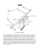
CLEARANCE TO COMBUSTIBLES 6
CHIMNEY AND VENTING Chimney required for the GBU070 is 4” Class “L” (also known as PL vent). A starting collar must be used to attach the venting system to the furnace. When connecting into a Class “A” or masonry chimney an approved 4” liner MUST be used to prevent back drafting of the chimney. EXISTING CLASS “A” CHIMNEY: Run 4” Class “L” connector from the furnace connection to a positive connection with the class “A” chimney. AN APPROVED 4” LINER MUST BE USED IN CLASS “A” CHIMNEYS.
VERTICAL CHIMNEY’S The chimney that this unit is connected to (Class “L”, all fuel or masonry) should extend above the roofline of adjacent buildings to prevent downdraft situations. 1. Class “L” connectors shall be installed without any downward pitch from the appliances and without any dips or sags. 2. Class “L” connectors shall be pitched upward from the appliance at least ¼” per foot. 3.
DUCTING PRIMARY FURNACE To install the GBU070 as a “Primary Furnace” first locate the furnace as near the chimney and as centralized with respect to heat distribution as practical. Follow all clearance to combustible requirements. Connect the ductwork to the furnace. Minimum supply plenum size: 14” x 14”, minimum return plenum size: 12” round.
ELECTRICAL REQUIREMENTS 1. Make sure that the power source conforms to the requirements of the furnace. Disconnect the power source before performing any maintenance or electrical work. 2. Connect the electrical power according to the appropriate wiring diagram on the following page. 3. Plug the power supply into a surge protected and grounded 15-amp branch circuit. The outlet must have the correct polarity.
TURNING OFF THE UNIT Turn the power switch to draft fan. Fuel will stop feeding but the draft fan will remain running. Let run until fire burns out completely. Set power switch to off. NOTE: Approximately 10 – 12 minutes should be enough time for fire to burn out. Time will vary depending on fuel type. MAINTENANCE 1. Check the ash pan regularly and empty as necessary. Dispose of the ashes in a metal container, and when cooled, bury them to prevent any spontaneous fires. 2.
BURNING CORN IN THE GBU070 NOTE: If your 070 was purchased as a corn unit the corn pot should already be installed. The corn pot utilizes a lift out cast iron inner liner that removes for easy cleaning. A rod will also be provided to lift the pot out of the furnace. 1. Your GBU070 will burn most types of clean-shelled corn. It is not necessary to mix corn with wood pellets although some people have had better success burning a 50/50 mix. 2.
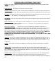
Let the pot cool completely to the touch and place into a bucket of water to dissolve the clinker. DO NOT PLACE HOT POT IN WATER; GBU070 FURNACE WIRING 2 WIRE LOW VOLTAGE THERMOSTAT YELLOW YELLOW RED ORANGE BLACK RED BLUE PURPLE SAFETY DISC BLACK WHITE RED FAN LIMIT CONTROL NOTE! INCORRECTLY INSTALLED CONTROL CAN CAUSE ELECTRIC SHOCK HAZARD OR DAMAGE TO LOW VOLTAGE CONTROLS. ON ALL GBU070 TRAGER MODELS THE BRASS JUMPER MUST BE REMOVED.
START UP INSTRUCTIONS – PELLET Now that your furnace has been properly installed, it’s time to fire it up! 1. Plug in the furnace. NOTE: Make sure you plug into a properly grounded, surgeprotected outlet that has proper polarity so as not to damage the circuitry of the control board. 2. Remove the rear panel of the furnace. Push in the white summer fan button located in the right side of unit in silver box, thus starting the blower.
START UP INSTRUCTIONS – CORN NOTE: Pellets are required to start your initial fire. 14. 15. 16. 17. 18. 19. 20. 21. 22. 23. 24. 25. 26. 27. Plug in the furnace. NOTE: Make sure you plug into a properly grounded, surgeprotected outlet that has proper polarity so as not to damage the circuitry of the control board. Remove the rear panel of the furnace. Push in the white summer fan button located in the right side of unit in silver box, thus starting the blower.
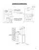
PRIMARY CONTROL OII 350S SEQUENCE OF OPERATION The Traeger OII 350S primary control is a high-tech, state of the art computer. The control performs the function of piloting the system when the thermostat does not call for heat. It conserves fuel consumption. Power In FUSE RED LIGHT INDICATOR The computer board is protected by a 3-amp fuse. There are many manufacturers of this fuse. Fuses are readily available at your local hardware or auto parts store. i.e. Napa Balkamp #782-1046 AGC 3.
TROUBLE SHOOTING GUIDE Tools Essential for Trouble Shooting 1. 2. 3. 4. Furnace Installation and Operation manual Circuit Tester / Volt Meter Molex pin Extractor Volt Meter ATTENTION: Before attempting any trouble shooting: 1. Check your outlet (for 070) or your wiring to breaker box (130 & 150) to insure proper polarity and grounding. 2. Check flue for any blockage. 3. Take time to clean burn pot and heat exchangers. 4.
STEP 3# CONFIRM DRAFT FAN OPERATION Be sure the main power switch is in the “Draft Fan” position. This will cause the draft fan to operate at full power (110v). The draft fan will operate at 70 – 75v when pilot draft switch is set at high. It will receive 60 – 65v in the medium position and zero volts in the off position when furnace is not feeding fuel. You should be able to hear the draft fan come to full speed. You can check movement of air by placing you hand over the fire pot.
INSTALLATION/ADJUSTMENT RELATED PROBLEMS PROBLEM: SOLUTION: PROBLEM: SOLUTION: Incomplete combustion, unburned fuel. 1. Adjust air shutter to a more open position. 2. Make sure of correct chimney, is chimney drafting? Is the chimney direct vented? Is it a tight basement? Outside air may be needed. What is fuel moisture? Burns fuel too quickly and may have difficulty holding a fire on pilot. Adjust air shutter to a more closed position.
OPERATOR RELATED PROBLEMS cont’d PROBLEM: Furnace will not feed fuel. SOLUTION: Check for blockage in metering cup. Is there fuel in the hopper? FUEL RELATED PROBLEMS Symptoms of Poor Fuel: 1. 2. 3. 4. 5. Unburned pellets Fire pot overflows as a result of high moisture content. Lack of heat. Excessive ash build-up. Incorrect size. PROBLEM NO HEAT # 1. Pellet fire has gone out during normal operation. CHECK CAUSES: 1, 2, 3, 7, 8, 10, 11, 13, 14, 15, 17, 21, 23, 24, 25, 26, 28, 36, 42 or 45. # 2.
#10. The blower cycles on and off too much. CHECK CAUSES: 9, 12, 22 or 59. #11. Furnace burns without regard to thermostat, overheats. CHECK CAUSES: 4, 8, 13, 14, 18, 30, 31, 33 or 50 #12. Furnace doesn't make as much heat as it used to. CHECK CAUSES: 5, 32, 37, 40, 53, 56, 57 or 59. #13. Circulating blower will not run at all. CHECK CAUSES: 9, 12, 17, 22, 45 or 56. #14. Remote thermostat is not accurate by thermometer. CHECK CAUSES: 18, 30, 31, 32, 33, 48 or 54. #15.
3. An impurity in the pellets has hung up the auger. Remedy: The cup is turning but the auger is not. Loosen the coupling on the auger and try to turn free. Do not force it. You may have to remove the auger to clear. 4. Fines and dust are accumulating in the burner compartment area. Remedy: Check the seal between the hopper and the burner flanges as well as the hopper seam seals. Reseal. 5. The heat exchanger is full of ash.
16. Improper stove ground. Remedy: Check the ground. Check the outlet. Just because there is a three-prong outlet receptacle does not mean that there is a ground wire hooked up to it, and then where does that ground wire go to? This appliance must be properly grounded. Also remember that the primary control grounds itself to the junction box, so never work on the unit with the primary control off the junction box with the power on. 17. Loose wiring connection. Remedy: Check power location with tester.
28. Too much chimney draft. Remedy: Check draw with a draft gauge. Maximum draft .08 inches. If draw exceeds .08 reduce chimney outlet to accomplish. 29. Too little draft. Remedy: Check draw of chimney with a draft gauge. Minimum draft .04 inches. May have to add more chimney. 30. Improper thermostat location. Remedy: Relocate thermostat to location that reflects better overall desired temperature scheme. 31. Thermostat set too high. Remedy: Turn it down to a more comfortable setting. 32.
43. Undersized or overloaded service wiring. Remedy: Call your electrical contractor. 44. Power surge. Remedy: Call your electrical contractor. 45. Power short in unit. Remedy: Locate short circuit and correct. 46. Pellets in hopper are giving off an odor. Remedy: Change the brand of pellets you are using, some species of wood have unpleasant odors. 47. Mounting bolts on the blower are loose. Remedy: Tighten the mounting bolts. 48. Remote thermostat is not level.
59. Aluminum air filter is dirty. Remedy: Remove from furnace and wash. 60. Inadequate return air. Too small, restricted, or is pulling unconditioned air. Remedy: Consult qualified HVAC ducting contractor for proper installation.
PARTS LIST 1. 2. 3. 4. 5. 6. 7. Hopper connector flange Pillow block ball bearing Cutting blades (2) ea. Fuel metering cup ½” lovejoy coupling Spider ½” lovejoy coupling F000221P F000505P F070513P-2 F070512P F000507P * F000505P F000507P * 8. Cup motor 9. Manual reset 10. Auger motor 11. Draft inducer 12. Auger/shaft assembly 13A. Fire pot (complete) ** 13B. Cast pot liner ** 13C.
WARRANTY NON TRANSFERABLE MODEL: _GBU070___________ SERIAL NUMBER: ____________________ DATE PURCHASED: __________________ FROM: __________________________ Complete Unit Warranty The manufacturer provides a warranty on all steel parts (except burn pot) and electrical components against defects in material or workmanship under normal use and maintenance for a period of one (1) year from the installation date.