DJ MIXER DJM-750 http://pioneerdj.com/support/ The Pioneer DJ support site shown above offers FAQs, information on software and various other types of information and services to allow you to use your product in greater comfort.
Contents How to read this manual In this manual, names of channels and buttons indicated on the product, names of menus in the software, etc., are indicated within square brackets ([ ]). (e.g. [MASTER] channel, [ON/OFF], [File] menu) Before start Features........................................................................................................ 3 Connections Rear panel....................................................................................................
Before start Before start Features This unit is a 4-channel DJ mixer carrying over the technology of the Pioneer DJM series, the world standard for club sound. It is not only equipped with a variety of functions for DJ performances, including USB sound card, BOOST COLOR FX, SOUND COLOR FX and BEAT EFFECT, it also uses a high sound quality, high reliability design and a panel layout with high operability to provide powerful support for all DJ performances.
Connections Be sure to turn off the power and unplug the power cord from the power outlet whenever making or changing connections. Refer to the operating instructions for the component to be connected. Connect the power cord after all the connections between devices have been completed. Be sure to use the included power cord. Rear panel 1 2 3 For Europe 456 4 CH 4 OFF ON POWER LINE L R SEND L (MONO) f CH 2 LINE L e CH 1 CD/ LINE L MASTER2 L Turns this unit’s power on and off.
Connecting input terminals ! Analog player Cassette deck, CD player, etc.
Connecting to the control panel Be sure to connect using the included USB cable. About the driver software and setting utility software The driver software is required to input and output the sound of a computer using this unit’s built-in USB sound card. Prepare a computer on which a Windows or Mac operating system is installed and the proprietary driver software provided by Pioneer. When the driver software is installed, the settings utility software is installed at the same time.
OR ARISING OUT OF COURSE OF PERFORMANCE, COURSE OF DEALING OR USAGE OF TRADE, INCLUDING ANY WARRANTIES OF MERCHANTABILITY, FITNESS FOR A PARTICULAR PURPOSE, SATISFACTORY QUALITY, ACCURACY, TITLE OR NON-INFRINGEMENT. You agree that any breach of this Agreement’s restrictions would cause Pioneer irreparable harm for which money damages alone would be inadequate.
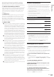
5 Proceed with installation according to the instructions on the screen. If [Windows Security] appears on the screen while the installation is in progress, click [Install this driver software anyway] and continue with the installation. ! When installing on Windows XP If [Hardware Installation] appears on the screen while the installation is in progress, click [Continue Anyway] and continue with the installation. ! When the installation program is completed, a completion message appears.
Adjusting the buffer size (when using Windows ASIO) Display the setting utility before starting. If an application using this unit as the default audio device (DJ software, etc.) is running, quit that application before adjusting the buffer size. Display the setting utility before starting. 1 Click the [MIXER OUTPUT] tab. Click the [ASIO] tab. Connections Setting the audio data output from this unit to the computer 2 Click the [Mixer Audio Output] pull-down menu.
Operation POWER MIC a USB CD/LINE a PHONO USB 1/2 CD/LINE a LINE USB 3/4 b OVER c d 0 -1 HI 0 -2 2 12 EQ/ EQ LOW - 7 -26 / 12 TALK ON OVER OFF - 7 -26 / 6 0 ISO -7 6 LOW -15 -15 -15 -24 -24 -24 -26 / 6 L dB -26 / 6 -26 / 6 dB BOOST NOISE JET e MIDI CRUSH FILTER SOUND COLOR FX e e e e v x START / STOP 4 5 LOW HEADPHONE CUE HI CUE BALANCE e k FADER START CH-2 FLANGER PHASER ROBOT FILTER VINYL BRAKE CH-3 TRANS HEAD PHONES MONO SPLIT f S
1 MIC LEVEL control (page 13) Adjusts the sound level output from the [MIC] channel. 2 EQ (HI, LOW) controls (page 13) Adjusts the sound quality of the [MIC] channel. 3 OFF, ON, TALK OVER selector switch (page 13) 4 ON/OFF button (page 15) Switches the MIDI function on and off. 5 START/STOP button (page 15) Sends the MIDI start/MIDI stop signals. 6 FADER START (CH-2, CH-3) buttons (page 12) These turn the fader start function on/off.
Basic Operation Outputting sound 1 Press [POWER] button. Turn on the power of this unit. 2 Switch the input selector switches. Selects the input sources for the different channels from among the devices connected to this unit. — [PHONO]: Selects the analog player connected to the [PHONO] terminals. — [CD/LINE], [LINE]: Selects the DJ player or cassette deck connected to the [CD/LINE] or [LINE] terminals. — [USB */*]: Selects the sound of the computer connected to the [USB] port. 3 Turn the [TRIM] control.
Start playback using the crossfader ! 1 Set the [CROSS FADER ASSIGN (A, THRU, B)] selector switch to [A] or [B]. 1 Set the [MONO, STEREO] selector switch to [STEREO]. 2 Press one of the [FADER START (CH-2, CH-3)] buttons. The sound’s left/right balance changes according to the direction in which the [BALANCE] control is turned and its position. ! Rotating to the rightmost position outputs only the right sound of stereo audio.
Advanced Operations 1 CH SELECT 2 1 2 3 4 MIC A B MST PARAMETER 3 AUTO TAP 6 4 BPM 5 % 7 ms 8 Number Name Descriptions SOUND BOOST BEAT COLOR COLOR EFFECT FX FX 1 Effect display section The name of the selected effect is displayed. — — 1 2 Channel select display section The name of the channel to which the effect is applied is displayed. 1 1 1 3 AUTO (TAP) [AUTO] lights when the BPM measurement mode is set to the auto mode. [TAP] lights when in the manual input mode.
5 Turn the [COLOR] control. When the control is turned, the effect is applied to the sound. Changes can be applied to the effect by turning the control quickly. Canceling the BOOST COLOR FX effect ! ! ! When the BPM is set using the [TAP] button, the beat fraction is set to [1/1] and the time of one beat (quarter note) is set as the effect time. The BPM can be set manually by turning the [TIME] control while pressing the [TAP] button. The BPM can be set in units of 0.
Types of effects BOOST COLOR FX/SOUND COLOR FX effect types Effect Name [BOOST] button status Descriptions [COLOR] control Off White noise generated inside this unit is mixed in to the sound of the channel via the filter and output. ! The volume can be adjusted by turning the [TRIM] controls for the respective channels. The sound quality can be adjusted by turning the [EQ/ISO (HI, MID, LOW)] controls.
SPIRAL 1 2 FILTER 1 This function adds a reverberation effect to the input sound. When the delay time is changed, the pitch changes simultaneously. The filter’s cutoff frequency changes according to the beat fraction set with the [BEAT c, d] buttons. Input sound turned off Fade-out Use these to set a time delay of 1/8 – 16/1 with respect to the time of one beat of the BPM. TIME control (parameter 2) Use this to set the delay time.
VINYL BRAKE 1 2 REV ROLL 1 2 The playing speed of the input sound changes according to the beat multiple set with the [BEAT c, d] buttons. The sound being input at the point when the [ON/OFF] button is pressed is recorded, and the recorded sound is reversed then output repeatedly according to the beat fraction set with the [BEAT c, d] buttons.
List of MIDI Messages ! ! “CC” is the abbreviation of “control change”. A control change is a type of MIDI signal used to transmit various types of control information, such as timbre, volume, etc. On this unit, values from 0 to 127 are output as CC mainly when controls and faders are operated. CC are also output when certain buttons are operated. “Note” is a MIDI term used when pressing or releasing notes on a piano or other keyboard.
Category SW Name EFFECT SELECT BEAT EFFECTS MIC Fader Start HEADPHONES Fader Start Trigger/Toggle Transmitted data CC 042 2 OFF=0, ON=127 ECHO Switch CC 055 2 OFF=0, ON=127 SPIRAL Switch CC 043 2 OFF=0, ON=127 REVERB Switch CC 054 2 OFF=0, ON=127 TRANS Switch CC 053 2 OFF=0, ON=127 FILTER Switch CC 059 2 OFF=0, ON=127 FLANGER Switch CC 050 2 OFF=0, ON=127 PHASER Switch CC 057 2 OFF=0, ON=127 ROBOT Switch CC 051 2 OFF=0, ON=127 VINYL BRAKE Switch CC 061 2
Changing the settings 1 Press the [SETUP (WAKE UP)] button for over 1 second. About the auto standby function The [USER SETUP] screen is displayed. ! To display the [CLUB SETUP] screen, first turn this unit’s power off, then press the [POWER] button while pressing the [SETUP (WAKE UP)] button. 2 Press the [BEAT c, d] button. Select the setting item. 3 Press the [TAP] button. The screen switches to the setting item’s setting value change screen.
Additional information Troubleshooting ! ! Incorrect operation is often mistaken for trouble or malfunction. If you think that there is something wrong with this component, check the points below. Sometimes the trouble may lie in another component. Inspect the other components and electrical appliances being used. If the trouble cannot be rectified after checking the items below, ask your nearest Pioneer authorized service center or your dealer to carry out repair work.
Problem Check Remedy Sound of a computer cannot be output from this unit. Are this unit and computer properly connected? Connect this unit and the computer directly using the included USB cable. (page 6) Are the audio output device settings properly set? Select this unit with the audio output device settings. For instructions on making settings for your application, see your application’s operating instructions.
Block Diagram MIC MIC LEVEL ADC DIGITAL MASTER CH1 CD/LINE FPGA DIT ADC PHONO MUTE PHONES MUTE MASTER 1 DAC Digital MASTER MIC CH1_ASEL_OUT CH2 CD/LINE CH1_Analog PHONES CH2_Analog MASTER CH3_Analog BOOTH ADC LINE MUTE CH2_ASEL_OUT DAC CH3 CD/LINE ADC LINE D SP CH4_Analog REC CH3_ASEL_OUT CH4 CD/LINE SEND RETURN MASTER 2 MUTE BOOTH MUTE REC MUTE SEND DAC ADC PHONO MUTE CH1_USB1/2 USB1/2 CH2_USB3/4 USB3/4 CH3_USB5/6 USB5/6 CH4_USB7/8 USB7/8 CH4_ASEL_
About trademarks and registered trademarks ! ! ! ! ! ! Pioneer is a registered trademark of PIONEER CORPORATION. Microsoft, Windows and Windows Vista are either registered trademarks or trademarks of Microsoft Corporation in the United States and/or other countries. Apple, Macintosh and Mac OS are trademarks of Apple Inc., registered in the U.S. and other countries. ASIO is a trademark of Steinberg Media Technologies GmbH.