
Owner's Manual


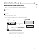
Table Of Contents
- Operation Manual
- Reset
- Clock Set
- Demo Mode
- Table of Contents
- Removing / Attaching Front Panel
- Parking Brake Interlock
- Touch Panel Calibration
- Parts & Controls
- Operation
- Basic Operation
- Tuner
- Playing Video
- Playing Audio
- Playing Still Images
- Bluetooth (130P5200BT)
- Introduction
- Calling a Number in the Phone Book
- Selecting a Number by Alphabet Search Mode
- Using the Missed, Received and Dialed Call Lists
- Setting Automatic Answering
- Adjusting the Other Party’s Listening Volume
- Ring Tone On / Off
- Using the Preset Dial Lists
- Making a Call by Entering Phone Number
- Setting the Private Mode
- Pairing from This Unit
- Using a Bluetooth Device to Pair
- Connecting to a Bluetooth Device Automatically
- Switching Visible Unit
- Displaying BD (Bluetooth Device) Address
- Entering PIN Code for Bluetooth Wireless Connection
- Registering a Connected Cellular Phone
- Bluetooth (130AVHP520 - Adapter Required)
- Introduction of Bluetooth Telephone Operations
- Bluetooth Audio Operations
- Setting Up for Bluetooth Audio
- Using the Missed, Received and Dialed Call Lists
- Setting Automatic Answering
- Switching the Ring Tone
- Using a Cellular Phone to Initiate a Connection
- Voice Recognition
- Connecting a Bluetooth Audio Player
- Connecting to a Bluetooth Device Automatically
- Displaying BD (Bluetooth Device) Address
- XM / SIRIUS Tuner
- HD Radio Tuner
- Using the AUX Sources
- Advanced Operations
- Tuner
- HD Radio
- iTunes Tagging
- Switching the Media File Type
- Operating the DVD Menu
- Operating This Unit’s iPod Function from your iPod
- Random
- Repeat
- Playing Videos from your iPod
- Browsing on the iPod
- DVD-Video Playback Options
- PBC Playback
- Selecting Tracks from the Track Title List
- Selecting Files from the File Name List
- Advanced Sound Retriever
- Audiobook Speed
- iPod Link Search
- DivX VOD Content
- Capture an Image in JPEG Files
- Changing the Wide Screen Mode
- XM / SIRIUS
- Changing the Picture Adjustment
- Setting Rear Monitor Output
- Touch Panel Calibration
- Using the AUX Sources
- Menu Operations
- Overview
- Common Menu Operations
- Audio Adjustments
- Setting Up the DVD Player
- System Settings
- AUX Source On / Off
- AV Input On / Off
- Rear Output & Subwoofer Controller
- Mute / Attenuation Settings
- Changing Languages for CAUTION
- Menu Language
- Clearing Bluetooth Memory (130P5200BT Only)
- Updating Bluetooth Connection Software (130P5200BT Only)
- Displaying the Bluetooth System Version (130P5200BT Only)
- Adjusting LCD Panel Slide Position
- Setting Automatic Open Function
- Switching the Warning Tone
- Rear View Camera
- Auto EQ
- Entertainment (Display) Settings
- Customizing Menus
- Troubleshooting
- Error Messages
- Specs
- Installation Manual
- Warranty

5
English
Connecting the units
Navigation unit
(AVIC-U220 (sold
separately)).
Antenna input
Tuner box (supplied)
Antenna cable (supplied)
80 cm
(2 ft. 7 in.)
IP-BUS cable
Pioneer IP-BUS
accessories
Connection method
1. Clamp the lead.
2. Clamp firmly with
needle-nosed pliers.
Note:
· The position of the parking brake switch depends on the vehicle model. For details,
consult the vehicle Owner
’s Manual or dealer.
Light green
Used to detect the ON/OFF status of the parking
brake. This lead must be connected to the power
supply side of the parking brake switch.
Blue/white
Connect to system control terminal of the power amp or
auto
-antenna relay control terminal (max. 300 mA 12 V DC).
Ground side
P
ower supply side
Parking brake
switch
W
ith a 2 speaker system, do not connect anything to the speaker leads
that are not connected to speakers.
Note:
· Change the initial setting of this unit (refer
to the Operation Manual). The subwoofer
output of this unit is monaural.
26 pin cable (Supplied with Navigation unit)
Insert the 26 pin cable in the direction
indicated in the figure.
Please contact your dealer to inquire
about the connectable navigation unit.
80 cm
(2 ft. 7 in.)