PORTUGUÊS (B) Æ…b¹b'« „öÝô« Ê«u « l “UN'« «c¼ r− M¹ ESPAÑOL WOÐdF « INSTALLATION MANUAL ENGLISH This product conforms to new cord colors. Los colores de los cables de este producto se conforman con un nuevo código de colores. As cores dos fios deste produto seguem um novo padrão de cores.
Contents Connecting the Units Connecting the Units ................................ 1 Connecting the power cord (1) .......................... 3 Connecting the power cord (2) .......................... 5 Connecting the system (A) ................................ 6 Connecting the system (B) ................................ 7 VIDEO Input / Output Connection .................. 8 Installation .................................................. 9 DIN Front/Rear-mount ......................................
OF OF O STAR STAR FRANÇAIS T ACC position F DEUTSCH O ESPAÑOL ACC N F ENGLISH • When an external power amp is being used with this system, be sure not to connect the blue/white lead to the amp’s power terminal. Likewise, do not connect the blue/white lead to the power terminal of the auto-antenna. Such connection could cause excessive current drain and malfunction. • To avoid short-circuiting, cover the disconnected lead with insulating tape.
Connecting the Units Connecting the power cord (1) 23 cm Refer to page 8. This product 15 cm 11 cm Antenna jack IP-BUS input (Blue) 40 cm Multi-CD player (sold separately) Blue/white To system control terminal of the power amp or Auto-antenna a relay control terminal (max. 300 mA 12 V DC) AV-BUS input IP-BUS cable Lightgreen Refer to page 5. Violet/white Fuse resistor Yellow/black If you use a cellular telephone, connect it via the Audio Mute lead on the cellular telephone.
Power amp (sold separately) Rear output (REAR OUTPUT) ENGLISH Connecting cords with RCA pin plugs (sold separately) Subwoofer output or non-fading output (SUBWOOFER OUTPUT or NON-FADING OUTPUT) Power amp (sold separately) ESPAÑOL Front output (FRONT OUTPUT) Power amp (sold separately) DEUTSCH System remote control + + ≠ ≠ Front speaker FRANÇAIS White Gray + + ≠ ≠ Front speaker White/black Green Gray/black Right Violet + ≠ ≠ Green/black Rear speaker ITALIANO + Violet/black + ≠
Connecting the Units Connecting the power cord (2) When using this product with a back-up camera, automatic switching to VIDEO video when the gear shift is moved to the REVERSE (R) position is possible. Connect the back-up camera to the VIDEO input. This product Note: • When you have completed lead wire connection, perform [VIDEO SETTING] correctly while referring to the Operation Manual. • It is necessary to set to [BACK UP CAMERA] in the [VIDEO SETTING] when connecting the back-up camera.
ENGLISH Connecting the system (A) This product Blue IP-BUS cable (supplied with TV tuner) IP-BUS cable AV-BUS cable (supplied with TV tuner) 40 cm Black ESPAÑOL 40 cm Black DVD player (sold separately) AV-BUS cable IP-BUS cable Blue AV-BUS cable Blue Hide-away TV Tuner (sold separately) DEUTSCH Black *1 Not used.
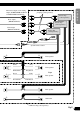
Connecting the Units Connecting the system (B) Remote sensor (supplied with Multi-DVD player) This Product Yellow (VIDEO INPUT or BACK UP CAMERA) Multi-DVD player (sold separately) < e.g. XDV-P9 > Blue Black AV-BUS cable (supplied with the TV tuner) Blue Black Not used. Blue Black IP-BUS cable (supplied with the TV tuner) IP-BUS cable (supplied with Multi-DVD player) Blue Black Yellow (FRONT VIDEO OUTPUT) Hide-away TV Tuner (sold separately)
ENGLISH VIDEO Input / Output Connection Commercially available portable video component with RCA output (or back-up camera) This product ESPAÑOL To video output Yellow (video input) 23 cm (VIDEO INPUT or BACK UP CAMERA) To audio outputs RCA cable (sold separately) To video input Display with RCA input jacks RCA cable (sold separately) Perform [VIDEO SETTING] correctly while referring to the Operation Manual.
Installation Note: • Before finally installing the unit, connect the wiring temporarily, making sure it is all connected up properly, and the unit and the system work properly. • Use only the parts included with the unit to ensure proper installation. The use of unauthorized parts can cause malfunctions. • Consult with your nearest dealer if installation requires the drilling of holes or other modifications of the vehicle.
2. Install side brackets. (Fig. 9) ENGLISH Side bracket ESPAÑOL Flush surface screw (5 × 6 mm) Fig. 9 3. Fastening the unit. (Fig. 10) DEUTSCH As a rule, secure with side brackets (large). Dashboard 182 53 FRANÇAIS Holder After inserting the holder into the dashboard, then select the appropriate tabs according to the thickness of the dashboard material and bend them. (Install as firmly as possible using the top and bottom tabs. To secure, bend the tabs 90 degrees.
Installation 7 When the installation space is not very deep When installing in a shallow space, secure with side brackets (small). In this case, stick conceal tape on parts that protrude from the dashboard. Holder After inserting the holder into the dashboard, then select the appropriate tabs according to the thickness of the dashboard material and bend them. (Install as firmly as possible using the top and bottom tabs. To secure, bend the tabs 90 degrees.
2. Fastening the unit to the factory radio mounting bracket. (Fig. 13) (Fig. 14) ENGLISH Select a position where the screw holes of the bracket and the screw holes of this product become aligned (are fitted), and tighten the screws at 2 places on each side. Use any of binding screws (4 × 3 mm), binding screws (5 × 6 mm) or flush surface screws (5 × 6 mm), depending on the shape of the screw holes in the bracket. *1 Use binding screws (4 × 3 mm) only. *1 *1 ESPAÑOL DEUTSCH Fig.
PIONEER CORPORATION 4-1, MEGURO 1-CHOME, MEGURO-KU, TOKYO 153-8654, JAPAN PIONEER ELECTRONICS (USA) INC. P.O. Box 1540, Long Beach, California 90801-1540, U.S.A. TEL: (800) 421-1404 PIONEER EUROPE NV Haven 1087, Keetberglaan 1, B-9120 Melsele, Belgium TEL: (0) 3/570.05.11 PIONEER ELECTRONICS ASIACENTRE PTE. LTD. 253 Alexandra Road, #04-01, Singapore 159936 TEL: 65-6472-1111 PIONEER ELECTRONICS AUSTRALIA PTY. LTD.