Français Deutsch Français Italiano Nederlands INSTALLATION MANUAL English This product conforms to CEMA cord colors. Le code de couleur des câbles utilisé pour ce produit est conforme à CEMA.
Contents Connecting the Units Connecting the Units ................................ 1 Connecting the system ...................................... 3 Connecting the power cord (1) .......................... 4 Connecting the power cord (2) .......................... 5 When connecting to separately sold power amp ............................................................ 7 When connecting with a rear view camera ...... 9 When connecting the external video component and the display ......................
F O Deutsch STAR STAR T ACC position OF OF O Español ACC N F English • When an external power amp is being used with this system, be sure not to connect the blue/white lead to the amp’s power terminal. Likewise, do not connect the blue lead to the power terminal of the auto-antenna. Such connection could cause excessive current drain and malfunction. • To avoid a short-circuit, cover the disconnected lead with insulating tape. Insulate the unused speaker leads without fail.
Connecting the Units Connecting the system 40 cm (1 ft. 4 in.) Yellow 15 cm (5-7/8 in.) 26 pin cable Black Navigation unit (e.g. AVIC-880DVD) (sold separately) Violet This product 30 pin cable (supplied) 3m (9 ft. 10 in.) 3m (9 ft. 10 in.) Blue Antenna cable (supplied) IP-BUS input (Blue) Violet 3m (9 ft. 10 in.) Hide-away unit (supplied) Antenna jack 21 pin cable (supplied) Blue Black 10 cm (3-7/8 in.) 15 cm (5-7/8 in.
Connecting the power cord (1) English Español Hide-away unit Deutsch Fuse holder Français Yellow To terminal always supplied with power regardless of ignition switch position. Black (ground) To vehicle (metal) body. Italiano Black ≠ Black/white + Center speaker Nederlands Fig.
Connecting the Units Connecting the power cord (2) See the section “When connecting with a rear view camera”. Violet/white Blue When the source is selected the tuner, a control signal is output. To Auto-antenna relay control terminal. If the car features a glass antenna, connect to the antenna booster power supply terminal (max. 300 mA 12 V DC). This product Yellow/black If you use an equipment with Mute function, wire this lead to the Audio Mute lead on that equipment.
English WARNING Español LIGHT GREEN LEAD AT POWER CONNECTOR IS DESIGNED TO DETECT PARKED STATUS AND MUST BE CONNECTED TO THE POWER SUPPLY SIDE OF THE PARKING BRAKE SWITCH. IMPROPER CONNECTION OR USE OF THIS LEAD MAY VIOLATE APPLICABLE LAW AND MAY RESULT IN SERIOUS INJURY OR DAMAGE. Connection method 1. Clamp the lead. 2. Clamp firmly with needle-nosed pliers. Deutsch Note: • The position of the parking brake switch depends on the vehicle model.
Connecting the Units When connecting to separately sold power amp Center output (CENTER OUTPUT) 23 cm (9 in.) This product Subwoofer output (SUBWOOFER OUTPUT) 23 cm (9 in.) Rear output (REAR OUTPUT) 15 cm (5-7/8 in.) Noise filter (small) Lock tie Front output (FRONT OUTPUT) 15 cm (5-7/8 in.) Blue/white When the source is switched ON, a control signal is output. To system control terminal of the power amp (max. 300 mA 12 V DC). See the section “Attaching the noise filters”.
English Power amp (sold separately) Power amp (sold separately) Español RCA cables (sold separately) Power amp (sold separately) Deutsch Power amp (sold separately) Français System remote control Left Right Front speaker Rear speaker Rear speaker Italiano Front speaker Nederlands Subwoofer Center speaker Perform these connections when using the optional amplifier. Fig.
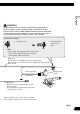
Connecting the Units When connecting with a rear view camera When using this product with a rear view camera, automatic switching to video from a rear view camera when the gear shift is moved to REVERSE (R) position is possible. WARNING: • USE INPUT ONLY FOR REVERSE OR MIRROR IMAGE REAR VIEW CAMERA. OTHER USE MAY RESULT IN INJURY OR DAMAGE. CAUTION: • The screen image may appear reversed.
Hide-away unit English This product Pioneer recommends the use of a camera which outputs mirror reversed images, otherwise screen image may appear reversed. 8m (26 ft. 3 in.) Rear view camera To video output Deutsch 15 cm (5-7/8 in.) Español RCA cable (sold separately) CAUTION Extension lead (supplied) Fuse resistor Français Violet/white Of the two lead wires connected to the back lamp, connect the one in which the voltage changes when the gear shift is in the REVERSE (R) position.
Connecting the Units When connecting the external video component and the display To audio outputs External video component (sold separately) To video output RCA cables (sold separately) Hide-away unit RCA cables (sold separately) To audio inputs Display with RCA input jacks To video input Fig. 7 • It is necessary to set to AV INPUT in SETUP when connecting the external video component.
Attaching the noise filters To prevent the noise, use the supplied noise filters correctly. English This product Noise filter (large) Noise filter (small) Español Noise filter (large) Lock tie Lock tie Lock tie Deutsch Noise filter (large) Speaker leads Other than speaker leads Hide-away unit Français Noise filter (small) Italiano Noise filter (large) Lock tie Noise filter (large) Nederlands Lock tie Fig.
Installation Note: • Before making a final installation of the unit, temporarily connect the wiring to confirm that the connections are correct and the system works properly. • Use only the parts included with the unit to ensure proper installation. The use of unauthorized parts can cause malfunctions. • Consult with your nearest dealer if installation requires the drilling of holes or other modifications of the vehicle.
DIN Front/Rear-mount DIN Front-mount Before installing the unit Installation with the rubber bush 1. Decide the position of the side brackets. (Fig. 12) When installing in a shallow space, change the position of side brackets. In this case, stick conceal tape on parts that protrude from the dashboard. Español • Remove the frame and the holder. (Fig.
Installation 2. Install the unit into the dashboard. (Fig. 13) After inserting the holder into the dashboard, then select the appropriate tabs according to the thickness of the dashboard material and bend them. (Install as firmly as possible using the top and bottom tabs. To secure, bend the tabs 90 degrees.) Dashboard 182 Rubber bush 53 Screw DIN Rear-mount Installation using the screw holes on the side of the unit • Fastening the unit to the factory radio mounting bracket. (Fig. 14) (Fig. 15) (Fig.
• When installing in a shallow space, use the following screw holes. In this case, stick conceal tape on parts that protrude from the dashboard. If you do not operate the removing and attaching the front panel function, use the supplied fixing screws to fix the front panel to this unit. • Fix the front panel to the unit using fixing screws after removing the front panel. (Fig. 17) *1 *1 English Conceal tape Fixing the front panel Fixing screw Español Fig. 15 Screw Fixing screw Deutsch Fig.
Table des matières Raccordements des appareils Raccordements des appareils ................ 1 Raccordement du système ................................ 3 Branchement du cordon d’alimentation (1) ...... 4 Branchement du cordon d’alimentation (2) ...... 5 Raccordements à un amplificateur de puissance vendu séparément ...................... 7 Raccordements à une caméra de recul .............. 9 Raccordements à un appareil vidéo externe et à un écran ............................................
F O STAR STAR T Position ACC OF OF O Français ACC N F English bleu à la borne d’alimentation de l’antenne automatique. Un tel branchement pourrait causer une perte de courant excessive et un mauvais fonctionnement de l’appareil. • Pour éviter tout court-circuit, recouvrez les conducteurs débranchés d’un ruban isolant. En particulier, n’oubliez pas d’isoler les fils de hautparleur. Un court-circuit peut se produire si les fils ne sont pas isolés.
Raccordements des appareils Raccordement du système Jaune 40 cm 15 cm Câble péritel 26 broches Noir Unité de navigation (par ex. AVIC-880DVD) (vendu séparément) Violet Cet appareil Câble péritel 30 broches (fourni) 3m 3m Bleu Câble d’antenne (fourni) Entrée IP-BUS (Bleu) Violet 3m Appareil déporté (fourni) Jack d’antenne Câble péritel 21 broches (fourni) Bleu 10 cm Noir Prise pour le micro “Auto-EQ&TA” Reportez-vous le mode d’emploi.
Branchement du cordon d’alimentation (1) English Appareil déporté Français Porte-fusible Jaune Vers une borne alimentée en permanence indépendamment de la clé de contact. Noir (masse) Fil de masse vers un élément en métal apparent de la voiture. Noir ≠ + Haut-parleur central Noir/blanc Fig.
Raccordements des appareils Branchement du cordon d’alimentation (2) Reportez-vous à la section “Raccordements à une caméra de recul”. Violet/blanc Bleu Si la source choisie est le syntoniseur, un signal de commande est émis. Vers la borne de commande de l’antenne motorisée. Si le véhicule est doté d’une antenne intégrée à une vitre, reliez ce conducteur à la borne d’alimentation du booster d’antenne (maximum 300 mA, 12 V CC).
English AVERTISSEMENT Français LE FIL VERT CLAIR SUR LE CONNECTEUR D’ALIMENTATION A POUR BUT DE DETECTER L’ETAT DE STATIONNEMENT DU VEHICULE ET DOIT ETRE CONNECTE AU COTE ALIMENTATION DU COMMUTATEUR DU FREIN A MAIN. UNE CONNEXION OU UNE UTILISATION INCORRECTE DE CE FIL PEUT VIOLER LA LOI APPLICABLE ET PEUT ENTRAINER DES BLESSURES GRAVES OU DES DOMMAGES SERIEUX. Méthode de connexion 1. Serrez le conducteur. 2. Serrez fermement avec une pince à mâchoires pointues.
Raccordements des appareils Raccordements à un amplificateur de puissance vendu séparément Sortie centrale (CENTER OUTPUT) 23 cm Cet appareil Sortie pour haut-parleur d’extrêmes graves (SUBWOOFER OUTPUT) 23 cm Sortie arrière (REAR OUTPUT) Filtre de bruit (petit) 15 cm Attache Sortie avant (FRONT OUTPUT) 15 cm Bleu/blanc Lorsque la source est mise en service, un signal de commande est émis. Vers la borne de commande d’ensemble de l’amplificateur de puissance (maximum 300 mA, 12 V CC).
English Amplificateur de puissance (vendu séparément) Amplificateur de puissance (vendu séparément) Français Câbles à fiches Cinch (RCA) (vendu séparément) Amplificateur de puissance (vendu séparément) Amplificateur de puissance (vendu séparément) Télécommande d’ensemble Gauche Droit Haut-parleur avant Haut-parleur avant Haut-parleur arrière Haut-parleur arrière Haut-parleur d’extrêmes graves Haut-parleur central Réalisez ces connexions si vous utilisez l’amplificateur optionnel. Fig.
Raccordements des appareils Raccordements à une caméra de recul Si vous utilisez cet appareil associé à une caméra de recul, la sélection automatique de la vidéo provenant de la caméra de recul est possible dès que le sélecteur de vitesse est placé sur la position REVERSE (R). AVERTISSEMENT: • UTILISEZ CETTE ENTRÉE UNIQUEMENT POUR UNE CAMÉRA FOURNISSANT UNE IMAGE INVERSÉE, COMME DANS UN MIROIR. TOUTE AUTRE UTILISATION POURRAIT ENTRAÎNER DES BLESSURES OU DES DOMMAGES.
English Appareil déporté Cet appareil Français Câble à fiches Cinch (RCA) PRÉCAUTION Pioneer conseille l’utilisation d’une caméra qui fournit des images inversées, comme dans un miroir; dans le cas contraire, l’image sur l’écran sera inverse. Caméra de recul À la sortie vidéo Conducteur rallonge (fourni) 15 cm 8m Violet/blanc Des deux conducteurs connectés au feu de recul, connectez celui pour lequel la tension change quand le sélecteur de vitesse est sur la position REVERSE (R).
Raccordements des appareils Raccordements à un appareil vidéo externe et à un écran Aux sorties audio Appareil vidéo externe (vendu séparément) À la sortie vidéo Câbles à fiches Cinch (RCA) (vendu séparément) Appareil déporté Câbles à fiches Cinch (RCA) (vendu séparément) Vers les entrées audio Écran muni de prises d’entrée Cinch (RCA) Vers l’entrée vidéo Fig. 7 • Il est nécessaire d’adopter l’option AV INPUT de SETUP si un appareil vidéo externe est connecté.
Fixation des filtres de bruit Pour éviter les bruits parasites, utilisez comme il convient les filtres de bruit fournis. English Cet appareil Filtre de bruit (grand) Français Filtre de bruit (grand) Filtre de bruit (petit) Attache Attache Attache Conducteur autre que ceux de la liaison aux haut-parleurs Câbles de liaison aux haut-parleurs Filtre de bruit (grand) Appareil déporté Filtre de bruit (petit) Filtre de bruit (grand) Attache Filtre de bruit (grand) Attache Fig.
Installation Remarque: • • Avant d’effectuer l’installation définitive, reliez provisoirement les appareils entre eux pour vous assurer qu’ils fonctionnent correctement, individuellement et ensemble. • Pour obtenir une bonne installation, n’utiliser que les pièces de l’appareil. L’utilisation de pièces non prévues risque de causer un mauvais fonctionnement. • Consulter le concessionnaire le plus proche si l’installation nécessite le percement de trous ou toute autre modification du véhicule.
Montage DIN avant/arrière 1. Décidez où placer les supports latéraux. (Fig. 12) Lors de l’installation dans une cavité peu profonde, modifiez l’emplacement des supports latéraux. Dans ce cas, collez du ruban adhésif de masquage sur les parties qui dépassent du tableau de bord. • Retirez le cadre et le support. (Fig.
Installation 2. Installez l’appareil dans le tableau de bord. (Fig. 13) Montage DIN arrière Après avoir introduit le support dans le tableau de bord, sélectíonnez les languettes appropriées en fonction de l’épaisseur du matériau du tableau de bord et courbez-les. (Assurez le maintien aussi solidement que possible en utilisant les languettes inférieures et supérieures. Cela fait, courbez les languettes de 90 degrés.
Ruban adhésif de masquage Fixation du panneau avant Si vous ne désirez pas employer les dispositions attachées à la dépose et à la pose du panneau avant, utilisez les vis de fixation fournies pour assurer la fixation du panneau avant de l’appareil. *1 *1 Vis de fixation Français • Fixez le panneau avant à l’appareil en utilisant les vis de maintien après avoir déposé le panneau avant. (Fig. 17) English • Lors de l’installation dans une cavité peu profonde, utilisez les perçages filetés ci-dessous.
PIONEER CORPORATION 4-1, MEGURO 1-CHOME, MEGURO-KU, TOKYO 153-8654, JAPAN PIONEER ELECTRONICS (USA) INC. P.O. Box 1540, Long Beach, California 90801-1540, U.S.A. TEL: (800) 421-1404 PIONEER EUROPE NV Haven 1087, Keetberglaan 1, B-9120 Melsele, Belgium TEL: (0) 3/570.05.11 PIONEER ELECTRONICS ASIACENTRE PTE. LTD. 253 Alexandra Road, #04-01, Singapore 159936 TEL: 65-6472-7555 PIONEER ELECTRONICS AUSTRALIA PTY. LTD.