Black plate (1,1) English Installation Manual Manuel d’installation Français NAVIGATION AV SYSTEM SYSTEME DE NAVIGATION AV SISTEMA DI NAVIGAZIONE AV SISTEMA DE NAVEGACIÓN AV AV NAVIGATIESYSTEEM Deutsch Nederlands 1 Español AVIC-F77DAB AVIC-F70DAB AVIC-F970DAB AVIC-F970BT AVIC-F9770DAB AVIC-F9770BT Italiano NAVIGATIONS-/AV-SYSTEM
Black plate (2,1) Contents Precautions Your new product and this manual 3 Important safeguards 3 Connection Precautions before connecting the system 5 Before installing this product 5 To prevent damage 6 – Notice for the blue/white lead 6 Parts supplied 7 Connecting the power cord (1) 8 Connecting the power cord (2) 10 Connecting the system 12 Connecting to separately sold power amp 13 Connecting an iPhone, iPod, Android device or a MirrorLink™ device 14 Attaching identification labels to USB cables 16 Co
Black plate (3,1) Section Precautions 01 English Your new product and this manual Important safeguards ! The navigation features of this product (and the rear view camera option if purchased) are intended solely to aid you in the operation of your vehicle. It is not a substitute for your attentiveness, judgement and care when driving. ! Never use this product to route to hospitals, police stations, or similar facilities in an emergency. Please call the appropriate emergency number.
Black plate (4,1) Section 01 Precautions ! Certain country and government laws may prohibit or restrict the placement and use of this product in your vehicle. Please comply with all applicable laws and regulations regarding the use, installation and operation of this product.
Black plate (5,1) Section Connection WARNING Do not take any steps to tamper with or disable the handbrake interlock system which is in place for your protection. Tampering with or disabling the handbrake interlock system could result in serious injury or death. CAUTION ! If you decide to perform the installation yourself, and have special training and experience in the mobile electronics installations, please carefully follow all of the steps in the installation manual.
Black plate (6,1) Section 02 Connection To prevent damage WARNING F ! When the ignition switch is turned on (ACC ON), a control signal is output through the blue/white lead. Connect to an external power amp’s system remote control terminal, the auto-aerial relay control terminal, or the aerial booster power control terminal (max. 300 mA 12 V DC). The control signal is output through the blue/white lead, even if the audio source is switched off.
Black plate (7,1) Section Connection 02 English Parts supplied This product Power cord GPS aerial Microphone USB cable (2 pcs.) USB cable identification labels Lock tie*1 Vehicle Bus conversion cable*2 Notes ! (*1) These parts are supplied with AVICF77DAB. ! (*2) These parts are supplied with AVICF77DAB, AVIC-F70DAB and AVICF970DAB.
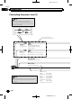
Black plate (8,1) Section 02 Connection Connecting the power cord (1) Note Depending on the types of vehicles, the function of *2 and *4 may be different. In this case, be sure to connect *1 to *4 and *3 to *2 as shown in the figure. *2 *1 *4 *3 Connect leads of the same colour to each other. Yellow (*2) Back-up (or accessory) Yellow (*1) To terminal supplied with power regardless of ignition switch position.
Black plate (9,1) Section Connection 02 English This product 14 cm Power supply Yellow/black (MUTE) If you use equipment with a mute function, connect that equipment to the Audio Mute lead. If not, keep the Audio Mute lead free of any connections. Note Fuse (10 A) Power cord Audio source will be set to mute or attenuate, while the following sounds will not be muted or attenuated. For details, refer to Operation Manual.
Black plate (10,1) Section 02 Connection Connecting the power cord (2) Pink (CAR SPEED SIGNAL INPUT) This product is connected here to detect the distance the vehicle travels. Always connect the vehicle’s speed detection circuit. Failure to make this connection will increase errors in the vehicle’s location display.
Black plate (11,1) Section Connection 02 English This product Power supply Power cord Violet/white (REVERSE-GEAR SIGNAL INPUT) This is connected so that this product can detect whether the vehicle is moving forwards or backwards. Connect the violet/white lead to the lead whose voltage changes when the reverse gear is engaged.
Black plate (12,1) Section 02 Connection Connecting the system F77DAB F70DAB F970DAB Vehicle Bus adapter input Please refer to the instruction manual for the Vehicle Bus adapter (sold separately). Vehicle Bus conversion cable 15.8 cm F77DAB F70DAB F970DAB DAB aerial input CAUTION: For improved Digital Radio reception, make sure a Digital Radio aerial with phantom power input (active type) is used. Pioneer recommends using AN-DAB1 or CA-AN-DAB.001 (sold separately).
Black plate (13,1) Section Connection 02 Power amp (sold separately) RCA cables Rear outputs (REAR OUTPUT) English Connecting to separately sold power amp (sold separately) Power amp (sold separately) 15 cm Power amp (sold separately) Front outputs (FRONT OUTPUT) This product Power supply White, Red (SWL, SWR) Power cord Blue/white To system control terminal of the power amp (max. 300 mA 12 V DC).
Black plate (14,1) Section 02 Connection Connecting an iPhone, iPod, Android device or a MirrorLink™ device Find your device and the function you want to operate from the list below, and refer to the page for the connection. iPhone 6 Plus/iPhone 6/iPhone 5s/iPhone 5c/iPhone 5 iPod (audio) Refer to Connecting via the USB port on page 16. F77DAB Refer to Connecting via the HDMI port on page 17. AppRadio Mode F70DAB F970DAB F970BT Refer to Connecting via the RGB input on page 17.
Black plate (15,1) Section Connection 02 English Android device F77DAB AppRadio Mode F77DAB F70DAB Android Auto HDMI port Refer to Connecting an Android device with an HDMI port on page 19. MHL port Refer to Connecting an Android device with an MHL port on page 19. Refer to Connecting the Android or MirrorLink™ device on page 20. Note For any of the connections mentioned above, aha and AVICSYNC App are available for use.
Black plate (16,1) Section 02 Connection Attaching identification labels to USB cables Attach identification labels to USB cables before installing this product in a vehicle. 1 Connect USB cables to the USB port 1 and 2 on the rear of this product. 2 Attach the identification labels corresponding to each port to the USB cables as illustrated below. Attach the “PORT 1” label to the USB cable connected to the USB port 1. Attach the “PORT 2” label to the USB cable connected to the USB port 2.
Black plate (17,1) Section Connection 02 F77DAB Connecting via the RGB input F70DAB F970DAB F970BT The following cables are required for the connection. ! HDMI interface cable for iPod / iPhone (CD-IH202) (sold separately) ! USB interface cable for iPod / iPhone (CDIU52) (sold separately) ! Lightning Digital AV Adapter (Apple Inc. products) (sold separately) USB port 1 This product HDMI port USB cable 1.5 m English Connecting via the HDMI port The following cables are required for the connection.
Black plate (18,1) Section 02 Connection Connecting an iPhone with 30-pin connector Notes ! For details on how to connect an external device using a separately sold cable, refer to the manual for the cable. ! For details concerning the connection, operations and compatibility of iPhone, refer to Operation Manual. Connecting via the RGB input The USB interface cable for iPod / iPhone (CDIU201S) (sold separately) is required for the connection.
Black plate (19,1) Section Connection 02 Connecting an Android device with an MHL port F77DAB English Connecting the Android™ device This product App Connectivity Kit (CD-AH200) (sold separately) is required for the connection. Notes ! For details on how to connect an external device using a separately sold cable, refer to the manual for the cable. ! For details concerning the connection and operations of Android device, refer to Operation Manual.
Black plate (20,1) Section 02 Connection Connecting the Android or MirrorLink™ device The USB interface cable for use with Android or MirrorLink™ devices (CD-MU200) (sold separately) is required for the connection. This product Securing the High Speed HDMI® Cable F77DAB Be sure to fix the High Speed HDMI® Cable with the lock tie, when you connect the external device with the High Speed HDMI® Cable. 1 Insert the High Speed HDMI® Cable into the HDMI port.
Black plate (21,1) Section Connection 02 English Connecting a rear view camera Rear view camera (ND-BC6) (sold separately) When this product is used with a rear view camera, it is possible to automatically switch from the video to rear view image when the gearstick is moved to REVERSE (R). Camera View mode also allows you to check what is behind you while driving. To video output RCA cable (supplied with ND-BC6) WARNING USE INPUT ONLY FOR REVERSE OR MIRROR IMAGE REAR VIEW CAMERA.
Black plate (22,1) Section 02 Connection Connecting the external video component Connecting the video component This product Using AV input You can connect an external video component or external camera to this product.
Black plate (23,1) Section Connection 02 CAUTION This product AUX input Be sure to use a mini-jack AV cable (CD-RM10) (sold separately) for wiring. If you use other cables, the wiring position might differ resulting in disturbed images and sounds.
Black plate (24,1) Section 02 Connection Connecting an HDMI device Connecting the rear display F77DAB This product This product Yellow (V OUT) Rear audio output HDMI port Mini pin plug cable (sold separately) High Speed HDMI® Cable (sold separately) To audio inputs HDMI device (sold separately) Notes ! For details concerning the operations of HDMI device, refer to Operation Manual. ! When you connect the High Speed HDMI® Cable, use the lock tie to fix it securely.
Black plate (25,1) Section Installation CAUTION ! Never install this product in places where, or in a manner that: — Could injure the driver or passengers if the vehicle stops suddenly. — May interfere with the driver’s operation of the vehicle, such as on the floor in front of the driver’s seat, or close to the steering wheel or gearstick. ! Make sure there is nothing behind the dashboard or panelling when drilling holes in them.
Black plate (26,1) Section 03 Installation ! Before making a final installation of this product, temporarily connect the wiring to confirm that the connections are correct and the system works properly. For AVIC-F77DAB and AVICF70DAB users Do not install this product in a position where the opening of the LCD panel is obstructed by any obstacles, such as the gearstick.
Black plate (27,1) Section Installation 03 Before installing this product 1 Remove the trim ring. Extend top and bottom of the trim ring outwards to remove the trim ring. 1 Do not cover this area. ! The semiconductor laser will be damaged if it overheats, so don’t install this product anywhere hot — for instance, near a heater outlet. Parts supplied 1 Trim ring 2 Insert the supplied extraction keys into both sides of the unit until they click into place. 3 Parts marked (*) are pre-installed.
Black plate (28,1) Section Installation 03 1 Dashboard 2 Holder 3 Installation using the screw holes on the side of this product Install this product into the holder. 1 % Fastening this product to the factory radio-mounting bracket. Position this product so that its screw holes are aligned with the screw holes of the bracket, and tighten the screws at three locations on each side.
Black plate (29,1) Section Installation 03 English Installing the GPS aerial Parts supplied CAUTION Do not cut the GPS aerial lead to shorten it or use an extension to make it longer. Altering the aerial cable could result in a short circuit or malfunction and permanent damage to this product. GPS aerial Metal sheet Installation notes ! The aerial should be installed on a level surface where radio waves will be blocked as little as possible.
Black plate (30,1) Section 03 Installation When installing the aerial inside the vehicle (on the dashboard or rear shelf) WARNING Do not install the GPS aerial over any sensors or vents on the dashboard of the vehicle, as doing so may interfere with the proper functioning of such sensors or vents and may compromise the ability of the metal sheet under the GPS aerial to properly and securely affix to the dashboard. 2 1 Make sure the surface is free of moisture, dust, grime, oil, etc.
Black plate (31,1) Section Installation 03 ! Install the microphone in a place where its direction and distance from the driver make it easiest to pick up the driver’s voice. ! Be sure to turn off (ACC OFF) the product before connecting the microphone. 2 Attach the microphone clip to the sun visor. 1 English Installing the microphone Parts supplied 2 Microphone Double-sided tape Mounting on the sun visor 1 Fit the microphone lead into the groove.
Black plate (32,1) Section 03 Installation Installation on the steering column 1 Detach the microphone base from the microphone clip by sliding the microphone base while pressing the tab. 1 Adjusting the microphone angle 2 4 1 2 3 4 1 Double-sided tape 2 Clamps Use separately sold clamps to secure the lead where necessary inside the vehicle. The microphone angle can be adjusted. 3 Microphone Tab Microphone base Microphone clip 2 Mount the microphone on the steering column.
Black plate (33,1) Section After installation 1 Reconnect the negative (–) terminal of the vehicle’s battery. First, double-check that all connections are correct and that this product is installed correctly. Reassemble all vehicle components that you previously removed. Then reconnect the negative (–) cable to the negative (–) terminal of the battery. 2 5 Drive down an unobstructed road until the GPS starts receiving the signal normally.
Black plate (34,1) Sommaire Précautions Votre nouveau produit et ce manuel 35 Importantes mesures de sécurité 36 Connexion Précautions à prendre avant de brancher le système 37 Avant d’installer ce produit 37 Pour éviter toute détérioration 38 – Remarque concernant le fil bleu/ blanc 38 Pièces fournies 39 Branchement du cordon d’alimentation (1) 40 Branchement du cordon d’alimentation (2) 42 Branchement du système 44 Connexion à un amplificateur de puissance vendu séparément 45 Connexion d’un iPhone, iPod
Black plate (35,1) Section Précautions Votre nouveau produit et ce manuel Si l’icône suivante s’affiche, la description s’applique uniquement au modèle indiqué. par ex. F77DAB Français ! La fonction de navigation de ce produit (et la caméra de rétrovisée en option le cas échéant) est uniquement destinée à vous assister lors de la conduite de votre véhicule. Elle n’autorise en aucun cas un relâchement de votre attention, de votre jugement et de votre vigilance pendant la conduite.
Black plate (36,1) Section 01 Précautions Importantes mesures de sécurité AVERTISSEMENT Pioneer vous recommande de ne pas installer ce produit vous-même. Ce produit doit être exclusivement installé par un professionnel. Nous recommandons que seul le personnel d’entretien Pioneer agréé, qui dispose d’une formation et d’une expérience spéciales dans l’électronique mobile, configure et installe ce produit. N’INTERVENEZ JAMAIS SUR CE PRODUIT VOUS-MÊME.
Black plate (37,1) Section Connexion Précautions à prendre avant de brancher le système AVERTISSEMENT ATTENTION ! Si vous décidez de réaliser l’installation vous-même, et possédez une expérience spéciale en installation d’électronique automobile, veuillez suivre attentivement toutes les étapes du manuel d’installation. ! Attachez tous les fils avec des colliers ou des serre-câbles. Ne laissez aucun fil à nu. ! Ne raccordez pas directement le fil jaune conducteur de ce produit à la batterie du véhicule.
Black plate (38,1) Section 02 Connexion Pour éviter toute détérioration AVERTISSEMENT F O STAR T STAR T Position ACC OF ACC O N F N OF ! Utilisez des haut-parleurs de plus de 50 W (valeur de sortie) et avec une impédance comprise entre 4 W et 8 W. N’utilisez pas de haut-parleurs 1 W à 3 W avec cet appareil. ! Le câble noir est mis à la masse. Veuillez mettre à la masse ce câble séparément de la masse des produits haute tension tels que les amplificateurs de puissance.
Black plate (39,1) Section Connexion 02 Pièces fournies Antenne GPS Français Ce produit Cordon d’alimentation Microphone Câble USB (2 pièces) Étiquettes d’identification des câbles USB Attache de blocage*1 Câble de conversion du bus du véhicule*2 Remarques ! (*1) Ces pièces sont fournies avec AVICF77DAB. ! (*2) Ces pièces sont fournies avec AVICF77DAB, AVIC-F70DAB et AVIC-F970DAB.
Black plate (40,1) Section 02 Connexion Branchement du cordon d’alimentation (1) Remarque En fonction des types de véhicules, la fonction de *2 et *4 peut être différente. Dans ce cas, veillez à connecter *1 à *4 et *3 à *2 comme illustré dans la figure. *2 *1 *4 *3 Connectez ensemble les fils de même couleur. Jaune (*2) Secours (ou accessoire) Jaune (*1) Vers la borne fournie avec l’alimentation quelle que soit la position du contacteur d’allumage.
Black plate (41,1) Section Connexion 02 Ce produit 14 cm Français Jaune/noir (MUTE) Si vous utilisez un équipement avec une fonction silence, connectez cet équipement sur le fil Audio Mute. Dans le cas contraire, ne rien connecter sur ce fil. Alimentation Remarque Fusible (10 A) Cordon d’alimentation La source audio sera coupée ou atténuée, alors que les sons suivants ne seront ni coupés ni atténués. Pour en savoir plus, reportez-vous au Manuel de fonctionnement.
Black plate (42,1) Section 02 Connexion Branchement du cordon d’alimentation (2) Rose (CAR SPEED SIGNAL INPUT) Ce produit est connecté ici pour détecter la distance parcourue par le véhicule. Toujours connecter le circuit de détection de vitesse du véhicule. Ne pas procéder à cette connexion augmente les erreurs dans l’afficheur d’emplacement du véhicule.
Black plate (43,1) Section Connexion 02 Français Ce produit Alimentation Cordon d’alimentation Violet/blanc (REVERSE-GEAR SIGNAL INPUT) Il est connecté afin que ce produit puisse détecter si le véhicule avance ou recule. Connectez le fil violet/blanc sur le fil dont la tension varie lorsque la marche arrière est enclenchée.
Black plate (44,1) Section 02 Connexion Branchement du système F77DAB F70DAB F970DAB Entrée d’adaptateur du bus du véhicule Reportez-vous au manuel d’instructions de l’adaptateur du bus du véhicule (vendu séparément). Câble de conversion du bus du véhicule 15,8 cm F77DAB F70DAB F970DAB Entrée d’antenne DAB AVERTISSEMENT : Pour une réception radio numérique améliorée, assurez-vous qu’une antenne radio numérique avec entrée d’alimentation fantôme (type actif) est utilisée.
Black plate (45,1) Section Connexion 02 Connexion à un amplificateur de puissance vendu séparément Amplificateur de puissance (vendu séparément) Câbles RCA (vendus séparément) Sorties arrière (REAR OUTPUT) Français Amplificateur de puissance (vendu séparément) 15 cm Amplificateur de puissance (vendu séparément) Sorties avant (FRONT OUTPUT) Ce produit Alimentation Blanc, rouge (SWL, SWR) Bleu/blanc Vers la borne de commande du système d’amplificateur de puissance (300 mA 12 VCC max.).
Black plate (46,1) Section 02 Connexion Connexion d’un iPhone, iPod, appareil Android ou appareil MirrorLink™ Trouvez votre appareil et la fonction que vous voulez utiliser dans la liste ci-dessous, puis reportez-vous à la page concernant la connexion. iPhone 6 Plus/iPhone 6/iPhone 5s/iPhone 5c/iPhone 5 iPod (audio) Reportez-vous à la page 48, Connexion via le port USB. F77DAB Reportez-vous à la page 49, Connexion via le port HDMI.
Black plate (47,1) Section Connexion 02 Appareil Android F77DAB AppRadio Mode Port MHL Reportez-vous à la page 51, Connexion d’un périphérique Android via un port MHL. Reportez-vous à la page 52, Connexion d’un appareil Android ou MirrorLink™. Remarque Pour n’importe quelles des connexions mentionnées ci-dessus, aha et AVICSYNC App sont disponibles pour l’utilisation. Français F77DAB F70DAB Android Auto Port HDMI Reportez-vous à la page 51, Connexion d’un périphérique Android via un port HDMI.
Black plate (48,1) Section 02 Connexion Apposition d’étiquettes d’identification aux câbles USB Connexion d’un iPhone avec connecteur Lightning Apposez les étiquettes d’identification aux câbles USB avant d’installer ce produit dans un véhicule. ! Pour en savoir plus sur la connexion d’un périphérique externe à l’aide d’un câble vendu séparément, reportez-vous au manuel du câble.
Black plate (49,1) Section Connexion 02 Connexion via le port HDMI = Pour en savoir plus, reportez-vous à la page 52, Fixation du câble HDMI® haute vitesse. F77DAB Port USB 1 Ce produit Connexion via l’entrée RGB F70DAB F970DAB F970BT Les câbles suivants sont nécessaires pour la connexion. ! Câble d’interface VGA/USB pour iPod / iPhone (CD-IV202AV) (vendu séparément) ! Câble d’interface USB pour iPod / iPhone (CD-IU52) (vendu séparément) ! Adaptateur Lightning vers VGA (produits Apple Inc.
Black plate (50,1) Section 02 Connexion Connexion d’un iPhone avec connecteur à 30 broches Remarques ! Pour en savoir plus sur la connexion d’un périphérique externe à l’aide d’un câble vendu séparément, reportez-vous au manuel du câble. ! Pour en savoir plus sur la connexion, le fonctionnement et la compatibilité d’un iPhone, reportez-vous au Manuel de fonctionnement. Connexion via l’entrée RGB Le câble d’interface USB pour iPod / iPhone (CD-IU201S) (vendu séparément) est nécessaire pour la connexion.
Black plate (51,1) Section Connexion 02 Connexion d’un périphérique Android™ Connexion d’un périphérique Android via un port MHL F77DAB Ce produit Français Le kit de connexion aux applications (CDAH200) (vendu séparément) est nécessaire pour la connexion. Remarques ! Pour en savoir plus sur la connexion d’un périphérique externe à l’aide d’un câble vendu séparément, reportez-vous au manuel du câble.
Black plate (52,1) Section 02 Connexion Connexion d’un appareil Android ou MirrorLink™ Le câble d’interface USB utilisé avec les appareils Android ou MirrorLink™ (CD-MU200) (vendu séparément) est nécessaire pour la connexion. Ce produit Fixation du câble HDMI® haute vitesse F77DAB Veillez à fixer le câble HDMI® haute vitesse à l’aide de l’attache de blocage lorsque vous connectez un périphérique externe à l’aide du câble HDMI® haute vitesse. 1 Insérez le câble HDMI® haute vitesse dans le port HDMI.
Black plate (53,1) Section Connexion Connexion d’une caméra de rétrovisée 02 Caméra de rétrovisée (ND-BC6) (vendu séparément) Quand ce produit est utilisé avec une caméra de rétrovisée, il est possible de commuter automatiquement entre le signal vidéo et l’image de rétrovisée quand le levier de vitesse est placé sur la position REVERSE (R). Le mode Vue Caméra vous permet également de vérifier ce qu’il y a derrière le véhicule quand vous conduisez.
Black plate (54,1) Section 02 Connexion Connexion d’un élément vidéo externe Connexion d’un composant vidéo Ce produit Utilisation de l’entrée AV Vous pouvez connecter un élément vidéo externe ou une caméra externe à ce produit.
Black plate (55,1) Section Connexion 02 Utilisation d’une entrée AUX Ce produit Entrée AUX ATTENTION Veillez à utiliser un câble AV mini-jack (CD-RM10) (vendu séparément) pour le raccordement. Si vous utilisez un autre type de câble, la position du raccordement pourrait différer, entraînant une déformation du son et des images.
Black plate (56,1) Section 02 Connexion Connexion d’un périphérique HDMI Connexion de l’afficheur arrière F77DAB Ce produit Ce produit Jaune (V OUT) Sortie audio arrière Port HDMI Câble connecteur mini-prise (vendu séparément) Câble HDMI haute vitesse (vendu séparément) ® Vers les entrées audio Appareil HDMI (vendu séparément) Remarques ! Pour en savoir plus sur le fonctionnement du périphérique HDMI, reportez-vous au Manuel de fonctionnement.
Black plate (57,1) Section Installation Précautions à prendre avant l’installation 03 ! ATTENTION ! ! ! ! Français ! Ne jamais installer ce produit dans un endroit ou de telle sorte qu’il : — risque de blesser le conducteur ou les passagers en cas d’arrêt brusque. — puisse interférer avec les commandes de manœuvre du conducteur tel que sur le plancher, en face du siège conducteur, ou à proximité du volant ou du levier de vitesse.
Black plate (58,1) Section 03 Installation De plus, vous devez placer ou acheminer le fil d’antenne aussi loin que possible des autres fils d’antenne. Ne les attachez, ne les placez ou ne les acheminez pas ensemble, ni ne les croisez. Le bruit électromagnétique augmentera les risques d’erreurs d’affichage de l’emplacement du véhicule. Avant de procéder à l’installation ! Consultez le concessionnaire le plus proche si l’installation nécessite de percer des trous ou toute autre modification du véhicule.
Black plate (59,1) Section Installation 03 ! Lors de l’installation de l’appareil, laissez suffisamment d’espace derrière le panneau arrière pour permettre une dissipation correcte de la chaleur et enroulez tout câble gênant de façon qu’il n’obstrue pas les orifices de ventilation.
Black plate (60,1) Section Installation 03 Avant d’installer ce produit 1 Retirez l’anneau de garniture. Étirez vers l’extérieur la partie supérieure et inférieure de l’anneau de garniture pour le retirer. 2 Fixez le manchon de montage en utilisant un tournevis pour courber les pattes métalliques (90°) en place. 1 2 1 1 Tableau de bord 2 Support 1 Anneau de garniture 2 Insérez les clés de démontage fournies dans les deux côtés de l’appareil jusqu’au déclic.
Black plate (61,1) Section Installation 4 03 Attachez l’anneau de garniture. Si le cliquet interfère avec l’installation, vous pouvez le replier complètement vers le bas. 1 Français 3 1 2 1 Anneau de garniture 2 Fente Fixez l’anneau de garniture côté fente orientée vers le bas. 2 1 Support de montage radio d’usine 2 Tableau de bord ou console 3 Vis à tête bombée ou vis à tête plate Veillez à utiliser les vis fournies avec ce produit.
Black plate (62,1) Section 03 Installation Installation de l’antenne GPS Pièces fournies ATTENTION Ne coupez pas le câble d’antenne GPS pour le raccourcir et n’utilisez pas d’extension pour le rallonger. Le fait d’intervenir sur le câble d’antenne risque d’entraîner un courtcircuit ou un dysfonctionnement et d’endommager de manière irrémédiable ce produit. Antenne GPS Plaque métallique Remarques sur l’installation ! L’antenne doit être installée sur une surface plane bien réceptive aux ondes radio.
Black plate (63,1) Section Installation 03 Installation de l’antenne dans le véhicule (sur le tableau de bord ou la lunette arrière) AVERTISSEMENT 2 Français N’installez pas l’antenne GPS par dessus un capteur ou une bouche d’air du tableau de bord du véhicule, car cela pourrait perturber le fonctionnement normal du capteur ou de la bouche d’air et compromettre la capacité de la plaque métallique sous l’antenne GPS d’assurer une fixation correcte et sûre sur le tableau de bord.
Black plate (64,1) Section 03 Installation Installation du microphone 2 Fixez l’agrafe pour micro au pare-soleil. 1 ! Installez le microphone dans un endroit permettant une bonne réception de la voix du conducteur. ! Éteignez ce produit (ACC OFF) avant de connecter le microphone. Pièces fournies 2 Microphone Bande adhésive à double face Installation sur le pare-soleil 1 Insérez le fil du microphone dans la fente.
Black plate (65,1) Section Installation 03 Installation sur la colonne de direction 1 Retirez la base du microphone de l’agrafe pour micro en faisant glisser la base du microphone tout en enfonçant la languette. 2 4 1 2 3 4 3 Microphone Languette Base du microphone Agrafe pour micro 2 Montez le microphone sur la colonne de direction. Installez le microphone sur la colonne de direction, à distance du volant.
Black plate (66,1) Section Après l’installation 04 Après avoir installé ce produit 1 Raccordez à nouveau la borne négative (–) de la batterie du véhicule. Vérifiez une nouvelle fois que toutes les connexions ont été bien faites et que ce produit est correctement installé. Remettez en place les éléments démontés du véhicule, puis rebranchez le câble négatif (–) sur la borne négative (–) de la batterie.
Black plate (67,1) Sommario Precauzioni Il nuovo prodotto e il presente manuale 68 Misure di sicurezza importanti 69 Italiano Connessione Precauzioni prima di collegare il sistema 70 Prima di installare questo prodotto 70 Per evitare danni 71 – Informazione sul cavetto blu/ bianco 71 Parti in dotazione 72 Collegamento del cavo di alimentazione (1) 74 Collegamento del cavo di alimentazione (2) 76 Collegamento del sistema 78 Collegamento a un amplificatore in vendita separatamente 79 Collegamento di un iP
Black plate (68,1) Sezione 01 Precauzioni Il nuovo prodotto e il presente manuale ! Le caratteristiche di navigazione di questo prodotto (e la telecamera di visione posteriore, se acquistata) sono da considerare soltanto come un ausilio alla conduzione del proprio veicolo. Non devono mancare attenzione, giudizio e cautela del conducente durante la guida. ! Non utilizzare mai il prodotto per raggiungere ospedali, stazioni di polizia o altre destinazioni simili in un’emergenza.
Black plate (69,1) Sezione Precauzioni Misure di sicurezza importanti AVVERTENZA ! Ricordare di allacciare sempre la cintura di sicurezza durante l’uso dell’automobile. In caso di incidenti, le lesioni possono essere molto più gravi se la cintura di sicurezza non è allacciata correttamente. ! Le legislazioni di alcuni Paesi e governi possono impedire o limitare il montaggio e l’uso di questo prodotto nel veicolo.
Black plate (70,1) Sezione 02 Connessione Precauzioni prima di collegare il sistema AVVERTENZA Non manomettere in alcun modo o disabilitare il sistema di interblocco di sicurezza del freno a mano che è necessario per proteggere il conducente. In caso di manomissione o disabilitazione di tale sistema, è possibile che incidenti con conseguenti lesioni gravi o morte del conducente.
Black plate (71,1) Sezione Connessione 02 Per evitare danni AVVERTENZA OF O STAR T STAR T Posizione ACC F N OF ACC O N F Nessuna posizione ACC Informazione sul cavetto blu/ bianco Italiano ! Utilizzare diffusori con potenza superiore a 50 W (valore di uscita) e tra 4 W e 8 W (valore di impedenza). Non utilizzare diffusori con valori tra 1 W e 3 W per questa unità. ! Il cavetto nero è il cavo di terra.
Black plate (72,1) Sezione 02 Connessione Parti in dotazione Questo prodotto Antenna GPS Cavo USB (2 pezzi) Fascetta di bloccaggio*1 Cavo di alimentazione Microfono Etichette identificative del cavo USB Cavo di conversione Bus per veicolo*2 Note ! (*1) Parti in dotazione con il modello AVICF77DAB. ! (*2) Parti in dotazione con i modelli AVICF77DAB, AVIC-F70DAB e AVIC-F970DAB.
Black plate (73,1) Sezione Connessione 02 Italiano It 73 73
Black plate (74,1) Sezione 02 Connessione Collegamento del cavo di alimentazione (1) Nota A seconda del tipo di veicolo, la funzione di 2* e 4* potrebbe essere diversa. In questo caso, accertarsi di collegare 1* a 4* e 3* a 2* come mostrato in figura. *2 *1 *4 *3 Collegare insieme i cavi dello stesso colore. Giallo (*2) Riserva (o accessorio) Giallo (*1) Al terminale alimentato, indipendentemente dalla posizione dell’interruttore della chiave di avviamento.
Black plate (75,1) Sezione Connessione 02 Questo prodotto 14 cm Giallo/nero (MUTE) Se si utilizza un apparecchio dotato di funzione di silenziamento, collegarlo al cavo di silenziamento audio. In caso contrario, non collegare questo cavo. Alimentazione Cavo di alimentazione Italiano Fusibile (10 A) Nota La sorgente audio viene disattivata o attenuata, mentre i seguenti suoni restano attivi e non vengono attenuati. Per ulteriori informazioni, vedere il Manuale di funzionamento.
Black plate (76,1) Sezione 02 Connessione Collegamento del cavo di alimentazione (2) Rosa (CAR SPEED SIGNAL INPUT) Va collegato al prodotto per consentire la rilevazione della distanza dei veicoli in movimento. Collegare sempre il circuito di rilevamento della velocità del veicolo. In caso contrario, aumenterà la possibilità di errori nella visualizzazione della posizione del veicolo.
Black plate (77,1) Sezione Connessione 02 Questo prodotto Italiano Alimentazione Cavo di alimentazione Violetto/bianco (REVERSE-GEAR SIGNAL INPUT) Va collegato per consentire al prodotto di rilevare quando il veicolo si sta spostando in avanti o indietro. Collegare il cavetto viola/bianco al cavetto la cui tensione cambia quando è inserita la retromarcia.
Black plate (78,1) Sezione 02 Connessione Collegamento del sistema F77DAB F70DAB F970DAB Ingresso adattatore Bus per veicolo Fare riferimento al manuale di istruzioni per informazioni sull’adattatore Bus per veicolo (venduto separatamente). Cavo di conversione Bus per veicolo 15,8 cm F77DAB F70DAB F970DAB Ingresso antenna DAB ATTENZIONE: Per ottenere una ricezione radio digitale controllare di utilizzare un’antenna radio digitale con ingresso di alimentazione phantom (tipo attivo).
Black plate (79,1) Sezione Connessione 02 Collegamento a un amplificatore in vendita separatamente Amplificatore di potenza (venduto separatamente) Cavi RCA (venduti separatamente) Uscite posteriori (REAR OUTPUT) Amplificatore di potenza (venduto separatamente) 15 cm Amplificatore di potenza (venduto separatamente) Uscite anteriori (FRONT OUTPUT) Italiano Questo prodotto Alimentazione Bianco, Rosso (SWL, SWR) Cavo di alimentazione Blu/bianco Al terminale di controllo del sistema dell’amplifica
Black plate (80,1) Sezione 02 Connessione Collegamento di un iPhone, iPod, dispositivo Android o dispositivo MirrorLink™ Trovare il proprio dispositivo e le funzioni che si desidera utilizzare nell’elenco di seguito riportato e fare riferimento alla pagina per il collegamento. iPhone 6 Plus/iPhone 6/iPhone 5s/iPhone 5c/iPhone 5 iPod (audio) Vedere Collegamento tramite la porta USB a pagina 82. F77DAB Vedere Collegamento tramite la porta HDMI a pagina 83.
Black plate (81,1) Sezione Connessione 02 Dispositivo Android F77DAB AppRadio Mode F77DAB F70DAB Android Auto Porta HDMI Vedere Collegamento di un dispositivo Android ad una porta HDMI a pagina 85. Porta MHL Vedere Collegamento di un dispositivo Android ad una porta MHL a pagina 86. Vedere Collegamento di un dispositivo Android o dispositivo MirrorLink™ a pagina 86. Nota È possibile utilizzare aha e AVICSYNC App per tutti i collegamenti sopra indicati.
Black plate (82,1) Sezione 02 Connessione Applicazione di etichette identificative ai cavi USB Applicare etichette identificative ai cavi USB prima di installare questo prodotto in un veicolo. 1 Collegare i cavi USB alle porte USB 1 e 2 sul retro di questo prodotto. 2 Applicare le etichette identificative corrispondenti a ogni porta ai cavi USB, come indicato nell’immagine in basso. Applicare l’etichetta “PORT 1” al cavo USB collegato alla porta USB 1.
Black plate (83,1) Sezione Connessione 02 Collegamento tramite la porta HDMI F77DAB Per il collegamento sono necessari i cavi seguenti. ! Cavo d’interfaccia HDMI per iPod / iPhone (CD-IH202) (venduto separatamente) ! Cavo d’interfaccia USB per iPod / iPhone (CD-IU52) (venduto separatamente) ! Adattatore da Lightning ad AV digitale (prodotti Apple Inc.
Black plate (84,1) Sezione 02 Connessione Porta USB 1 Questo prodotto Collegamento tramite l’ingresso AUX Per il collegamento è necessario il cavo di interfaccia USB per iPod / iPhone (CD-IU201V) (venduto separatamente). Porta USB 1 Questo prodotto Ingresso RGB iPhone con connettore Lightning Porta USB 2 Lightning to VGA Adapter (prodotti Apple Inc.
Black plate (85,1) Sezione Connessione 02 Collegamento tramite l’ingresso RGB Per il collegamento è necessario il cavo di interfaccia USB per iPod / iPhone (CD-IU201S) (venduto separatamente). Porta USB 1 Questo prodotto Collegamento dei dispositivi Android™ F77DAB Per il collegamento è necessario il kit di collegamento per applicazioni (CD-AH200) (venduto separatamente).
Black plate (86,1) Sezione 02 Connessione Collegamento di un dispositivo Android ad una porta MHL Questo prodotto Collegamento di un dispositivo Android o dispositivo MirrorLink™ Per il collegamento è necessario il cavo di interfaccia USB da utilizzare con dispositivi MirrorLink™ (CD-MU200) (venduto separatamente).
Black plate (87,1) Sezione Connessione 02 Fissaggio del cavo HDMI® ad alta velocità F77DAB Assicurarsi di fissare il cavo HDMI® ad alta velocità con la fascetta di bloccaggio quando si collega il dispositivo esterno con il cavo HDMI® ad alta velocità. 1 Inserire il cavo HDMI® ad alta velocità nella porta HDMI. Quando al prodotto si collega una telecamera di visione posteriore, innestando REVERSE (R) si può passare automaticamente dall’immagine video a quella trasmessa dalla telecamera stessa.
Black plate (88,1) Sezione 02 Connessione Collegamento di un componente video esterno Telecamera di visione posteriore (ND-BC6) (venduta separatamente) Uso di un ingresso AV All’uscita video Cavo RCA (fornito con ND-BC6) È possibile collegare un componente video esterno o una fotocamera esterna a questo prodotto.
Black plate (89,1) Sezione Connessione 02 Collegamento di un componente video Questo prodotto Uso dell’ingresso AUX Questo prodotto Ingresso AUX Cavo AV con mini-spinotto (CD-RM10) (venduto separatamente) 15 cm 23 cm Giallo (VIDEO INPUT) Rosso, bianco Giallo Cavi RCA (venduto separatamente) Alle uscite audio All’uscita video Cavi RCA (venduto separatamente) All’uscita video Componente video esterno (venduto separatamente) Nota Questa modalità è disponibile quando l’ingresso AV è impostato
Black plate (90,1) Sezione 02 Connessione ATTENZIONE Per il cablaggio, assicurarsi di usare un cavo AV con mini-spinotto (CD-RM10) (venduto separatamente). Se si usano altri cavi vi è la possibilità che la posizione di cablaggio possa variare e che le immagini e i suoni risultino disturbati.
Black plate (91,1) Sezione Connessione 02 Collegamento del display posteriore Questo prodotto Giallo (V OUT) Uscita audio posteriore Agli ingressi audio Italiano Cavo mini plug (venduto separatamente) Cavo RCA (venduto separatamente) All’ingresso video Display posteriore con connettori d’ingresso RCA (venduto separatamente) Quando si utilizza un display posteriore collegato a un’uscita video posteriore AVVERTENZA Non installare MAI il display posteriore in un luogo che permetta al conducente di
Black plate (92,1) Sezione 03 Installazione Precauzioni prima dell’installazione ! ATTENZIONE ! Non installare mai questo produtto in luoghi dove, o in maniera che: — Possa ferire il conducente o i passeggeri se il veicolo si arresta improvvisamente. — Possa interferire con le azioni del conducente del veicolo, come sul pavimento di fronte al sedile del conducente o vicino al volante o alla leva del cambio.
Black plate (93,1) Sezione Installazione Prima dell’installazione ! Rivolgersi al più vicino rivenditore se l’installazione richiede la trapanatura di fori o altre modifiche del veicolo. ! Prima di eseguire l’installazione definitiva di questo prodotto, collegare temporaneamente i cablaggi per verificare che i collegamenti siano corretti e che il sistema funzioni correttamente.
Black plate (94,1) Sezione 03 Installazione ! I cavi non devono coprire la zona mostrata nella figura sotto. Ciò è necessario per consentire agli amplificatori e al meccanismo di navigazione di dissipare il calore. Prima di installare questo prodotto 1 Rimuovere la cornice di finitura. Per rimuovere la cornice di finitura occorre tirarne verso l’esterno le parti superiore e inferiore. Non coprire questa zona.
Black plate (95,1) Sezione Installazione 2 Assicurare la fascetta di montaggio utilizzando un cacciavite per piegare le linguette metalliche (90°) in posizione. 03 4 Fissare la cornice di finitura. 1 2 3 1 Italiano 1 Cruscotto 2 Supporto 2 Installare il prodotto nel supporto. 1 Cornice di finitura 2 Scanalatura Fissare la cornice di finitura con il lato che presenta la scanalatura verso il basso.
Black plate (96,1) Sezione 03 Installazione Se la linguetta ostacola l'installazione, piegarla verso il basso. 1 3 2 1 Staffa di montaggio radio predisposta in fabbrica 2 Cruscotto o console 3 Vite a testa tonda o vite a testa piatta Assicurarsi di utilizzare le viti fornite con questo prodotto.
Black plate (97,1) Sezione Installazione 03 Installazione dell’antenna GPS Parti in dotazione ATTENZIONE Non tagliare il cavetto dell’antenna GPS per accorciarlo e non usare una prolunga per allungarlo. L’alterazione del cavo dell’antenna può causare cortocircuiti o malfunzionamenti e danni permanenti al prodotto. Antenna GPS Lastra metallica Note sull’installazione 1 Italiano ! L’antenna deve essere installata su una superficie piana dove le onde radio siano bloccate il meno possibile.
Black plate (98,1) Sezione 03 Installazione Quando si installa l’antenna all’interno del veicolo (sul cruscotto o sul piano portaoggetti posteriore) AVVERTENZA Non installare l’antenna GPS su eventuali sensori o aperture presenti sul cruscotto del veicolo poiché ciò potrebbe interferire con il corretto funzionamento di tali sensori e aperture e compromettere il corretto fissaggio della placca metallica dell’antenna GPS al cruscotto.
Black plate (99,1) Sezione Installazione 03 Installazione del microfono ! Installare il microfono in un luogo dove la sua direzione e distanza dal conducente rendano facile il rilevamento della voce. ! Accertarsi di spegnere il prodotto (ACC OFF) prima di collegare il microfono. 2 Fissare il morsetto del microfono al parasole. 1 Parti in dotazione Italiano 2 Microfono Nastro a doppio lato Montaggio sul parasole 1 Adattare il cavo del microfono nella fessura.
Black plate (100,1) Sezione 03 Installazione Installazione sulla colonna di sterzo 1 Scollegare la base del microfono dal morsetto facendola scorrere mentre si preme la linguetta. 1 2 2 4 1 2 3 4 3 Microfono Linguetta Base del microfono Morsetto del microfono 2 Montare il microfono sulla colonna di sterzo. Installare il microfono sulla colonna di sterzo, tenendolo lontano dal volante.
Black plate (101,1) Sezione Dopo l’installazione Dopo l’installazione del prodotto 1 Ricollegare il terminale negativo (–) della batteria del veicolo. Innanzitutto controllare due volte che tutti i collegamenti siano corretti e che questo prodotto sia installato correttamente. Rimontare tutti i componenti del veicolo precedentemente rimossi. Quindi ricollegare il cavo negativo (–) al terminale negativo (–) della batteria.
Black plate (102,1) Índice Precauciones Su nuevo producto y este manual Precauciones importantes 104 103 Conexión Precauciones antes de conectar el sistema 105 Antes de instalar este producto 105 Para impedir daños 106 – Aviso para el cable conductor azul/ blanco 106 Piezas suministradas 107 Conexión del cable de alimentación (1) 108 Conexión del cable de alimentación (2) 110 Conexión del sistema 112 Conexión al amplificador de potencia que se vende por separado 113 Conectar un iPhone, iPod, dispositivo
Black plate (103,1) Sección Precauciones Su nuevo producto y este manual Si se muestra el siguiente icono, la descripción es válida solo para el modelo que se muestra. p. ej. F77DAB Español ! Las funciones de navegación de este producto (y la opción de cámara de retrovisor, si dispone de ella) están pensadas únicamente para ayudarle en la conducción de su vehículo. Bajo ningún concepto deben considerarse como un sustituto de su atención, buen juicio y cuidado durante la conducción.
Black plate (104,1) Sección 01 Precauciones Precauciones importantes ADVERTENCIA Pioneer aconseja que no realice usted mismo la instalación del producto. Este producto se ha diseñado para que su instalación la realice únicamente un instalador profesional. Recomendamos que sólo el personal de servicio autorizado de Pioneer, que cuenta con formación especializada y experiencia en el campo de la electrónica móvil, instale y configure este producto.
Black plate (105,1) Sección Conexión Precauciones antes de conectar el sistema ADVERTENCIA No trate de forzar ni desactivar el sistema de interbloqueo del freno de mano que está activado para su protección. Si trata de forzarlo o desactivarlo, podrían producirse lesiones graves o incluso la muerte. PRECAUCIÓN ! No enrute cables que vayan a estar sometidos a altas temperaturas.
Black plate (106,1) Sección 02 Conexión Para impedir daños ADVERTENCIA F O STAR T STAR T Posición ACC OF ACC O N F N OF ! Utilice altavoces con capacidad superior a 50 W (valor de salida) y entre 4 W a 8 W (valor de impedancia). No utilice altavoces de 1 W a 3 W para esta unidad. ! El cable negro es de conexión a tierra. Conecte este cable a una toma de tierra distinta de productos de alta tensión, como por ejemplo, amplificadores de potencia.
Black plate (107,1) Sección Conexión 02 Piezas suministradas Este producto Cable de alimentación Micrófono Cable USB (2 piezas) Etiquetas de identificación del cable USB Presilla de sujeción*1 Cable de conversión para bus del vehículo*2 Español Antena GPS Notas ! (*1) Estas piezas se suministran con AVICF77DAB. ! (*2) Estas piezas se suministran con AVICF77DAB, AVIC-F70DAB y AVIC-F970DAB.
Black plate (108,1) Sección 02 Conexión Conexión del cable de alimentación (1) Nota Según los tipos de vehículos, la función de *2 y *4 puede ser diferente. En ese caso, asegúrese de conectar *1 a *4 y *3 a *2, tal y como se muestra en la figura. *2 *1 *4 *3 Conecte cables del mismo color. Amarillo (*2) Reserva (o accesorio) Amarillo (*1) Al terminal que recibe alimentación independientemente de la posición del interruptor de encendido.
Black plate (109,1) Sección Conexión 02 Este producto 14 cm Amarillo/negro (MUTE) Si utiliza un equipo con función de silenciamiento, conecte el equipo al cable de silenciamiento de audio. En caso contrario, deje este cable sin conectar. Fuente de alimentación Fusible (10 A) Cable de alimentación Nota Azul/blanco (*5) La posición de las clavijas del conector ISO variará en función de los tipos de vehículos. Conecte *5 y *6 cuando la clavija 5 sea un tipo de control de antena.
Black plate (110,1) Sección 02 Conexión Conexión del cable de alimentación (2) Rosa (CAR SPEED SIGNAL INPUT) Este producto se conecta aquí para detectar la distancia que el vehículo recorre. Conecte siempre el circuito de detección de velocidad del vehículo. Si no se realiza esta conexión, aumentarán los errores de visualización de la ubicación del vehículo.
Black plate (111,1) Sección Conexión 02 Este producto Fuente de alimentación Cable de alimentación Español Violeta/blanco (REVERSE-GEAR SIGNAL INPUT) Esta conexión se realiza para que este producto pueda detectar si el vehículo se está moviendo hacia delante o hacia atrás. Conecte el cable violeta/blanco al cable cuyo voltaje cambia cuando la palanca de cambios se coloca en la posición de marcha atrás.
Black plate (112,1) Sección 02 Conexión Conexión del sistema F77DAB F70DAB F970DAB Entrada del adaptador de bus del vehículo Consulte el manual de instrucciones para el adaptador de bus del vehículo (vendido por separado). Cable de conversión para bus del vehículo 15,8 cm F77DAB F70DAB F970DAB Entrada de antena DAB PRECAUCION: Para obtener una recepcion de radio digital optima, uitilice una antena para radio digital con entrada de alimentacion fantasma (phantom) (tipo activa).
Black plate (113,1) Sección Conexión 02 Conexión al amplificador de potencia que se vende por separado Amplificador de potencia (vendido por separado) Cables RCA (vendidos por separado) Salidas traseras (REAR OUTPUT) Amplificador de potencia (vendido por separado) 15 cm Amplificador de potencia (vendido por separado) Salidas frontales (FRONT OUTPUT) Este producto Español Blanco, Rojo (SWL, SWR) Fuente de alimentación Cable de alimentación Azul/blanco Al terminal de control del sistema del ampli
Black plate (114,1) Sección 02 Conexión Conectar un iPhone, iPod, dispositivo Android o dispositivo MirrorLink™ Encuentre su dispositivo y la función que desea manejar en la siguiente lista y, para más información acerca de la conexión, consulte la página. iPhone 6 Plus/iPhone 6/iPhone 5s/iPhone 5c/iPhone 5 iPod (audio) Consulte Conexión mediante el puerto USB en la página 116. F77DAB Consulte Conexión mediante el puerto HDMI en la página 117.
Black plate (115,1) Sección Conexión 02 Dispositivo Android F77DAB AppRadio Mode F77DAB F70DAB Android Auto Puerto HDMI Consulte Conexión de un dispositivo Android con un puerto HDMI en la página 119. Puerto MHL Consulte Conexión de un dispositivo Android con un puerto MHL en la página 120. Consulte Conectar el dispositivo Android o MirrorLink™ en la página 120. Aviso Para cualquiera de las conexiones mencionadas anteriormente, puede utilizar aha y AVICSYNC App.
Black plate (116,1) Sección 02 Conexión Colocación de etiquetas de identificación en los cables USB Conexión de un iPhone con conector Lightning Coloque etiquetas de identificación en los cables USB antes de instalar este producto en un vehículo. ! Para obtener más información sobre cómo conectar un dispositivo externo mediante un cable que se vende por separado, consulte el manual del cable.
Black plate (117,1) Sección Conexión 02 Conexión mediante el puerto HDMI F77DAB Se necesitan los siguientes cables para la conexión. ! Cable de interfaz HDMI para iPod / iPhone (CD-IH202) (vendido por separado) ! Cable de interfaz USB para iPod / iPhone (CD-IU52) (vendido por separado) ! Adaptador de conector Lightning a AV digital (producto de Apple Inc.
Black plate (118,1) Sección 02 Conexión Puerto USB 1 Este producto Conexión mediante la entrada AUX Para realizar la conexión es necesario un cable de interfaz USB para iPod / iPhone (CDIU201V) (vendido por separado). Puerto USB 1 Este producto Entrada RGB iPhone con conector Lightning Puerto USB 2 Entrada AUX Cable de extensión minijack (incluido con CD-IU201V) Adaptador de conector Lightning a VGA (producto de Apple Inc.
Black plate (119,1) Sección Conexión 02 Conexión mediante la entrada RGB Para realizar la conexión es necesario un cable de interfaz USB para iPod / iPhone (CDIU201S) (vendido por separado). Puerto USB 1 Este producto Conexión de dispositivos Android™ F77DAB Para realizar la conexión es necesario el kit de conectividad de aplicación (CD-AH200) (vendido por separado).
Black plate (120,1) Sección 02 Conexión Conexión de un dispositivo Android con un puerto MHL Este producto Conectar el dispositivo Android o MirrorLink™ Para realizar la conexión es necesario un cable de interfaz USB para el uso con dispositivos Android y MirrorLink™ (CD-MU200) (vendido por separado).
Black plate (121,1) Sección Conexión 02 Fijación del cable HDMI® de alta velocidad F77DAB Asegúrese de fijar el cable HDMI® de alta velocidad con la presilla de sujeción cuando conecte el dispositivo externo con el cable HDMI® de alta velocidad. 1 Inserte el cable HDMI® de alta velocidad en el puerto HDMI.
Black plate (122,1) Sección 02 Conexión Cámara de retrovisor (ND-BC6) (se vende por separado) Conexión del componente de vídeo externo Utilización de la entrada AV A la salida de vídeo Cable RCA (incluido con ND-BC6) Puede conectar un componente de vídeo externo o una cámara externa a este producto.
Black plate (123,1) Sección Conexión 02 Conexión del componente de vídeo Este producto Utilización de una entrada AUX Este producto Entrada AUX Cable AV minijack (CD-RM10) (vendido por separado) 15 cm 23 cm Rojo, blanco (AUDIO INPUT) Amarillo (VIDEO INPUT) Amarillo Cables RCA (se vende por separado) A la salida de vídeo Componente de vídeo externo (vendido por separado) Nota Este modo está disponible cuando el ajuste de entrada AV está establecido en “Fuente”.
Black plate (124,1) Sección 02 Conexión PRECAUCIÓN Asegúrese de utilizar un cable AV minijack (CDRM10) (se vende por separado) para el cableado. Si utiliza otros cables, la posición del cableado puede diferir, provocando imágenes y sonidos interrumpidos.
Black plate (125,1) Sección Conexión 02 Conexión de la pantalla trasera Este producto Amarillo (V OUT) Salida de audio trasera Cable RCA (se vende por separado) A las entradas de audio A la entrada de vídeo Español Cable miniconector (vendido por separado) Pantalla trasera con conectores de entrada RCA (vendido por separado) Uso de una pantalla trasera conectada a la salida de vídeo trasera ADVERTENCIA NUNCA instale la pantalla trasera en un punto que permita al conductor ver la fuente de vídeo
Black plate (126,1) Sección 03 Instalación Precauciones antes de la instalación PRECAUCIÓN ! Nunca instale este producto en lugares en los que, o de manera que: — Pudiese dañar al conductor o a los pasajeros si el vehículo se detuviese de repente. — Pudiese afectar a la conducción del vehículo, como por ejemplo en el suelo delante del asiento del conductor o cerca del volante o la palanca de cambios.
Black plate (127,1) Sección Instalación Además, debería colocar o enrutar cada cable de antena lo más lejos posible de otros cables de antena. No ate, coloque ni enrute los cables de forma conjunta, ni los cruce. El ruido electromagnético aumentará la posibilidad de que se produzcan errores en la pantalla de ubicación del vehículo. Antes de la instalación ! Póngase en contacto con su distribuidor más cercano si la instalación requiere la perforación de orificios u otras modificaciones del vehículo.
Black plate (128,1) Sección 03 Instalación ! Cuando instale el sistema, para garantizar una correcta dispersión del calor durante el uso de esta unidad, asegúrese de dejar un amplio espacio por detrás del panel trasero y enrollar los cables sueltos de modo que no bloqueen las aberturas de ventilación. Deje un amplio espacio Piezas suministradas Las piezas marcadas con un asterisco (*) están instaladas previamente.
Black plate (129,1) Sección Instalación Antes de instalar este producto 1 Extraiga el anillo embellecedor. Extienda la parte superior y la parte inferior del anillo embellecedor hacia fuera para extraer el anillo embellecedor. 03 2 Fije el manguito de montaje utilizando un destornillador para doblar las pestañas metálicas (90°) y colocarlas en su lugar.
Black plate (130,1) Sección Instalación 03 4 Coloque el anillo embellecedor. Si la pestaña interfiere con la instalación, puede doblarla para apartarla. 1 1 2 1 Anillo embellecedor 2 Ranura Coloque el anillo embellecedor con el lado que tiene una ranura mirando hacia abajo. Instalación utilizando los orificios de tornillo del lateral de este producto % Fije este producto al soporte de montaje de radio de fábrica.
Black plate (131,1) Sección Instalación 03 Instalación de la antena GPS Piezas suministradas PRECAUCIÓN No corte el cable de la antena GPS para reducir su longitud, ni utilice una extensión para alargarlo. La alteración del cable de la antena puede provocar un cortocircuito o una avería y daños permanentes en el producto. Antena GPS Hoja metálica Notas acerca de la instalación ! La antena debe instalarse en una superficie nivelada donde las ondas de radio queden bloqueadas lo menos posible.
Black plate (132,1) Sección 03 Instalación Cuando instale la antena en el interior del vehículo (en el tablero de instrumentos o en la bandeja trasera) ADVERTENCIA No instale la antena GPS sobre sensores o aberturas de ventilación en el tablero de instrumentos del vehículo, ya que eso puede afectar al funcionamiento correcto de tales sensores o aberturas de ventilación y puede poner en riesgo la habilidad de adherencia apropiada y segura de la hoja metálica por debajo de la antena GPS al tablero de instr
Black plate (133,1) Sección Instalación 03 Instalación del micrófono 2 Fije el clip del micrófono al parasol. 1 ! Instale el micrófono de tal forma que esté correctamente orientado y a la distancia correcta del conductor para que resulte fácil recoger la voz del conductor. ! Asegúrese de apagar (ACC OFF) el producto antes de conectar el micrófono. Piezas suministradas 2 Micrófono Cinta de doble cara 1 Coloque el cable del micrófono en la ranura.
Black plate (134,1) Sección 03 Instalación Instalación en la columna de dirección 1 Desconecte la base del micrófono del clip del mismo deslizándola a la vez que pulsa la lengüeta. 1 2 2 4 1 2 3 4 3 Micrófono Lengüeta Base del micrófono Clip del micrófono 2 Monte el micrófono en la columna de dirección. Instale el micrófono en la columna de dirección, manteniéndolo alejado del volante.
Black plate (135,1) Sección Después de la instalación Después de instalar este producto 1 Vuelva a conectar el terminal negativo (–) de la batería del vehículo. Primero, cerciórese de que todas las conexiones estén bien hechas y de que este producto esté instalado correctamente. Vuelva a instalar todos los componentes del vehículo que extrajo previamente. Y luego vuelva a conectar el cable negativo (–) al borne negativo (–) de la batería.
Black plate (136,1) Inhalt Vorsichtsmaßnahmen Ihr neues Produkt und diese Anleitung 137 Wichtige Sicherheitshinweise 138 Verbindung Vor dem Anschließen des Systems zu beachten 139 Vor dem Einbau dieses Produkts 139 Zur Vermeidung von Schäden 140 – Anmerkung zum blau/weißen Kabel 141 Mitgelieferte Teile 141 Stromkabel anschließen (1) 142 Stromkabel anschließen (2) 144 Anschluss des Systems 146 Anschluss an den separat erhältlichen Leistungsverstärker 147 Anschluss eines iPhone, iPod, Android- oder MirrorLi
Black plate (137,1) Abschnitt Vorsichtsmaßnahmen Ihr neues Produkt und diese Anleitung die mittels der Symbole angezeigten Modelle gilt. Wenn das folgende Symbol erscheint, trifft die Beschreibung nur auf das dargestellte Modell zu. z. B. F77DAB Deutsch ! Die Navigationsfunktionen dieses Produktes (und die Heckkameraoption, sofern erworben) dienen nur zu Ihrer Unterstützung beim Fahren Ihres Fahrzeugs. Sie sind keinesfalls ein Ersatz für Ihre Aufmerksamkeit und Umsicht beim Fahren.
Black plate (138,1) Abschnitt 01 Vorsichtsmaßnahmen Wichtige Sicherheitshinweise WARNUNG Pioneer empfiehlt, das Produkt nicht selbst einzubauen. Dieses Produkt ist für den Einbau durch professionelle Fachkräfte ausgelegt. Wir empfehlen, dass nur autorisierte Pioneer-Mitarbeiter, die entsprechend ausgebildet sind und Erfahrung im Bereich mobiler Elektronik haben, den Einbau des Produkts durchführen. FÜHREN SIE WARTUNGSARBEITEN AN DIESEM PRODUKT NIEMALS SELBST DURCH.
Black plate (139,1) Abschnitt Verbindung Vor dem Anschließen des Systems zu beachten WARNUNG Vermeiden Sie jegliche Eingriffe zur Manipulation oder Deaktivierung des Handbremsensperrsystems, da dieses Ihrer Sicherheit dient. Eine Manipulation oder Deaktivierung des Handbremsensperrsystems kann eine schwere Verletzung oder den Tod zur Folge haben. VORSICHT ! Die Kabel so verlegen, dass sie keinen hohen Temperaturen ausgesetzt werden.
Black plate (140,1) Abschnitt Verbindung Zur Vermeidung von Schäden WARNUNG ! Verwenden Sie Lautsprecher mit mehr als 50 W (Belastbarkeit) und 4 W bis 8 W (Impedanz). Verwenden Sie keine Lautsprecher mit 1 W bis 3 W für dieses Gerät. ! Das schwarze Kabel ist die Masseleitung. Dieses Kabel ist getrennt von Hochstromprodukten wie Leistungsverstärkern zu erden. Niemals zwei Geräte zusammen erden. Zum Beispiel muss die Masseleitung des Verstärkers getrennt von der Masseleitung dieses Produkts geerdet werden.
Black plate (141,1) Abschnitt Verbindung ! Die Anschlussstecker auf die gleichfarbigen Anschlüsse aufstecken (blauer Stecker auf blauen Anschluss, schwarz auf schwarz usw.) ! Einzelheiten zum Anschluss des Leistungsverstärkers und anderer Geräte siehe Benutzerhandbuch. Die Anschlüsse entsprechend ausführen. ! Wegen des eingebauten BPTL-Schaltkreises die *-Seite des Lautsprecherkabels nicht direkt erden oder die *-Seiten zweier Lautsprecherkabel verbinden.
Black plate (142,1) Abschnitt 02 Verbindung Stromkabel anschließen (1) Hinweis Je nach Fahrzeugtyp unterscheidet sich eventuell die Funktion von *2 und *4. Schließen Sie in diesem Fall *1 an 4* und *3 an *2 an, wie in der Abbildung dargestellt. *2 *1 *4 *3 Verbinden Sie jeweils Kabel mit den gleichen Farben. Gelb (*2) Speicherschutz (oder Zubehör) Gelb (*1) An einen Anschluss, der unabhängig von der Zündschalterposition unter Spannung steht.
Black plate (143,1) Abschnitt Verbindung 02 Dieses Produkt 14 cm Stromversorgung Gelb/Schwarz (MUTE) Schließen Sie ein Gerät mit Stummschaltungsfunktion an das Stummschaltungskabel an. Lassen Sie dieses Kabel anderenfalls unbenutzt. Hinweis Sicherung (10 A) Stromkabel Die Audioquelle wird stumm geschaltet oder gedämpft, während die folgenden Töne normal ausgegeben werden. Einzelheiten siehe Bedienungsanleitung.
Black plate (144,1) Abschnitt 02 Verbindung Stromkabel anschließen (2) Rosa (CAR SPEED SIGNAL INPUT) Dieses Produkt wird hier angeschlossen, um die zurückgelegte Entfernung des Fahrzeugs zu erkennen. Schließen Sie immer die Geschwindigkeits- Erkennungsschaltung des Fahrzeugs an. Wenn diese Verbindung nicht vorgenommen wird, erhöht sich die Fehlerabweichung in der Anzeige der Fahrzeugposition.
Black plate (145,1) Abschnitt Verbindung 02 Dieses Produkt Stromversorgung Stromkabel Deutsch Violett/Weiß (REVERSE-GEAR SIGNAL INPUT) Dieses Kabel muss angeschlossen sein, damit das Produkt erkennen kann, ob das Fahrzeug vorwärts oder rückwärts fährt. Das violett/weiße Kabel ist mit dem Fahrzeugkabel zu verbinden, dessen Spannung sich beim Einlegen des Rückwärtsgangs ändert.
Black plate (146,1) Abschnitt 02 Verbindung Anschluss des Systems F77DAB F70DAB F970DAB Fahrzeug-Bus-Adaptereingang Entnehmen Sie Details der Bedienungsanleitung des Fahrzeug-Bus-Adapters (separat erhältlich). FahrzeugbusKonvertierungskabel 15,8 cm F77DAB F70DAB F970DAB DAB-Antenneneingang ACHTUNG: Achten Sie darauf fur einen verbesserten Digitalradioempfang eine Digitalradioantenne mit Phantomspeisung (aktiver Typ) zu verwenden. Pioneer empfiehlt die Verwendung von AN-DAB1 oder CA-AN-DAB.
Black plate (147,1) Abschnitt Verbindung 02 Anschluss an den separat erhältlichen Leistungsverstärker Leistungsverstärker (separat erhältlich) Cinch-Kabels (separat erhältlich) Heckausgänge (REAR OUTPUT) Leistungsverstärker (separat erhältlich) 15 cm Leistungsverstärker (separat erhältlich) Vordere Ausgänge (FRONT OUTPUT) Dieses Produkt Stromversorgung Weiß, Rot (SWL, SWR) Stromkabel Deutsch Blau/Weiß An den Systemsteuerungsanschluss des Leistungsverstärkers (max. 300 mA,12 V DC).
Black plate (148,1) Abschnitt 02 Verbindung Anschluss eines iPhone, iPod, Android- oder MirrorLink™-Gerätes Suchen Sie in der nachfolgenden Liste nach Ihrem Gerät und der gewünschten Funktion und entnehmen Sie Details zum Anschluss der angegebenen Seite. iPhone 6 Plus/iPhone 6/iPhone 5s/iPhone 5c/iPhone 5 iPod (Audio) Siehe Anschluss über den USB-Anschluss auf Seite 150. F77DAB Siehe Anschluss über den HDMI-Anschluss auf Seite 151.
Black plate (149,1) Abschnitt Verbindung 02 Android-Gerät F77DAB AppRadio Mode F77DAB F70DAB Android Auto HDMI-Anschluss Siehe Anschluss eines Android-Geräts über den HDMI-Anschluss auf Seite 153. MHL-Anschluss Siehe Anschluss eines Android-Geräts über den MHL-Anschluss auf Seite 154. Siehe Anschluss eines Android- oder MirrorLink™-Gerätes auf Seite 154. Hinweis Für alle oben genannten Anschlüsse können die Optionen aha und AVICSYNC App verwendet werden.
Black plate (150,1) Abschnitt 02 Verbindung USB-Kabel mit Kennzeichnungsetiketten markieren Bevor Sie dieses Produkt in einem Fahrzeug einbauen, sollten Sie die USB-Kabel mit Kennzeichnungsetiketten markieren. 1 Verbinden Sie die USB-Kabel mit den USB-Anschlüssen 1 und 2 an der Rückseite dieses Produkts. 2 Befestigen Sie die Kennzeichnungsetiketten entsprechend des jeweiligen Anschlusses an den USB-Kabeln, wie unten abgebildet.
Black plate (151,1) Abschnitt Verbindung 02 Anschluss über den HDMIAnschluss F77DAB Die folgenden Kabel sind für einen Anschluss erforderlich. ! HDMI-Schnittstellenkabel für iPod / iPhone (CD-IH202) (separat erhältlich) ! USB-Schnittstellenkabel für iPod / iPhone (CD-IU52) (separat erhältlich) ! Lightning Digital AV Adapter (Produkt von Apple Inc.
Black plate (152,1) Abschnitt 02 Verbindung USB-Anschluss 1 Dieses Produkt Anschluss über den AUX-Eingang Der Anschluss erfolgt über ein USB-Schnittstellenkabel für iPod / iPhone (CD-IU201V) (getrennt erhältlich). USB-Anschluss 1 Dieses Produkt RGB-Eingang iPhone mit Lightning Connector Lightning auf VGA Adapter (Produkt von Apple Inc.
Black plate (153,1) Abschnitt Verbindung 02 Anschluss über den RGB-Eingang Der Anschluss erfolgt über ein USB-Schnittstellenkabel für iPod / iPhone (CD-IU201S) (separat erhältlich). USB-Anschluss 1 Anschluss des Android™-Geräts F77DAB Der Anschluss erfolgt über das App Connectivity Kit (CD-AH200) (separat erhältlich).
Black plate (154,1) Abschnitt 02 Verbindung Anschluss eines Android-Geräts über den MHL-Anschluss Dieses Produkt Anschluss eines Androidoder MirrorLink™-Gerätes Für den Anschluss ist das USB-Schnittstellenkabel zur Verwendung mit Android- oder MirrorLink™-Geräten (CD-MU200) erforderlich (getrennt erhältlich).
Black plate (155,1) Abschnitt Verbindung 02 Befestigen des High-SpeedHDMI®-Kabels F77DAB Verwenden Sie einen Kabelbinder, um das High-Speed-HDMI®-Kabel sicher zu befestigen, wenn ein externes Gerät über das HighSpeed-HDMI®-Kabel angeschlossen wird. 1 Stecken Sie das High-Speed-HDMI®Kabel in den HDMI-Anschluss. 2 Wickeln Sie den Kabelbinder um den Haken über dem HDMI-Anschluss und dem High-Speed-HDMI®-Kabel, und ziehen Sie ihn dann fest, um das High-Speed-HDMI®Kabel sicher zu befestigen.
Black plate (156,1) Abschnitt 02 Verbindung Anschluss einer externen Videokomponente Heckkamera (ND-BC6) (separat erhältlich) Verwendung eines AV-Eingangs An den Videoausgang Cinch-Kabel (mit ND-BC6 mitgeliefert) An dieses Produkt kann eine externe Videokomponenten oder externe Kamera angeschlossen werden.
Black plate (157,1) Abschnitt Verbindung 02 Anschluss einer Videokomponente Dieses Produkt Verwenden des AUX-Eingangs Dieses Produkt AUX-Eingang Mini-Buchsen-AV Kabel (CD-RM10) (separat erhältlich) 15 cm 23 cm Gelb (VIDEO INPUT) Rot, weiß (AUDIO INPUT) Rot, weiß Gelb Cinch-Kabels (separat erhältlich) An die Audioausgänge An den Videoausgang Hinweis Dieser Modus steht zur Verfügung, wenn der AVEingang auf “Quelle” gestellt ist. (Einzelheiten siehe Bedienungsanleitung.
Black plate (158,1) Abschnitt 02 Verbindung Anschluss eines HDMI-Geräts VORSICHT Verwenden Sie unbedingt das spezielle MiniBuchsen-AV-Kabel (CD-RM10) (separat erhältlich) für den Anschluss. Andere Kabel werden unter Umständen anders verlegt, was Bild- und Tonstörungen zur Folge haben kann.
Black plate (159,1) Abschnitt Verbindung 02 Anschluss des zusätzlichen Displays Dieses Produkt Gelb (V OUT) Hinterer Audioausgang Mini-Klinkenkabel (separat erhältlich) An die Audioeingänge Cinch-Kabel (separat erhältlich) An den Videoeingang Zusätzliches Display mit Cinch-Eingangsbuchsen (separat erhältlich) Deutsch Bei Verwendung eines zusätzlichen Displays, das an den hinteren Videoausgang angeschlossen ist WARNUNG Installieren Sie das zusätzliche Display NIEMALS so, dass der Fahrer während
Black plate (160,1) Abschnitt 03 Einbau Vor der Installation zu beachten VORSICHT ! Dieses Produkt niemals so einbauen, dass: — der Fahrer oder Beifahrer bei einem plötzlichen Bremsmanöver verletzt werden könnte. — der Fahrer bei der Bedienung des Fahrzeugs behindert wird, wie beispielsweise auf dem Boden vor dem Fahrersitz oder nahe dem Lenkrad oder Schalthebel.
Black plate (161,1) Abschnitt Einbau Zur Vermeidung elektromagnetischen Rauschens Um Störeinflüsse zu vermeiden sind die folgenden Bauteile so weit wie möglich von diesem Produkt, anderen Kabeln oder Leitungen zu installieren: ! Radioantenne (UKW, MW/LW) und Antennenkabel ! DAB-Antenne und Antennenkabel (für AVIC-F77DAB, AVIC-F70DAB und AVICF970DAB) ! GPS-Antenne und Antennenkabel Zusätzlich sollten Sie jedes Antennenkabel so weit wie möglich entfernt von anderen Antennenkabeln verlegen.
Black plate (162,1) Abschnitt 03 Einbau 5° 5° Mitgelieferte Teile Mit einem (*) markierte Teile sind vorinstalliert. ! Damit die bei Betrieb dieses Geräts entwikkelte Wärme richtig abgeleitet werden kann, sorgen Sie beim Einbau dafür, dass ausreichend Platz hinter der Rückwand bleibt, und wickeln Sie lockere Kabel so, dass diese keine Öffnungen blockieren können.
Black plate (163,1) Abschnitt Einbau 03 Vor dem Einbau dieses Produkts 1 Entfernen Sie den Abdeckring. Ziehen Sie die obere und die untere Seite des Abdeckrings nach außen, um den Abdeckring zu entfernen. 1 1 Abdeckring 2 Führen Sie die mitgelieferten Entriegelungsschlüssel bis zum Einrasten an beiden Seiten des Geräts ein. 3 2 Befestigen Sie den Montagerahmen mithilfe eines Schraubendrehers: Die Metallklammern sind in eine sichere Position (90°) zu biegen.
Black plate (164,1) Abschnitt Einbau 03 4 Bringen Sie den Abdeckring an. Wenn die Klinke bei der Installation im Weg ist, können Sie sie herabbiegen. 1 1 2 1 Abdeckring 2 Nut Befestigen Sie den Abdeckring mit nach unten zeigender Nut an der Seite. Installation mit Hilfe der Schraubenbohrungen an der Seite dieses Produkts % Befestigen Sie dieses Produkt an den vorinstallierten Radio-Montagebügeln.
Black plate (165,1) Abschnitt Einbau 03 Einbau der GPS-Antenne Mitgelieferte Teile VORSICHT Das GPS-Antennenkabel darf nicht verkürzt oder verlängert werden. Veränderungen am Antennenkabel können zu einem Kurzschluss oder einer Funktionsstörung und dauerhaften Beschädigung dieses Produkts führen. GPS-Antenne Metallblech Hinweise zur Befestigung ! Die Antenne ist auf einer ebenen Fläche zu befestigen, die für Funkwellen gut zugänglich sein sollte.
Black plate (166,1) Abschnitt 03 Einbau Einbau der Antenne im Fahrzeuginnenraum (auf dem Armaturenbrett oder der Hutablage) WARNUNG Installieren Sie die GPS-Antenne nicht über Sensoren oder Öffnungen am Armaturenbrett des Fahrzeugs, da dies den sachgemäßen Betrieb dieser Sensoren oder Öffnungen und die dauerhafte Befestigung der beeinträchtigen könnte. Außerdem könnte es in diesem Fall ggf. schwierig sein, das unter der GPS-Antenne befindliche Blech korrekt und sicher am Armaturenbrett zu befestigen.
Black plate (167,1) Abschnitt Einbau 03 Einbau des Mikrofons ! Bauen Sie das Mikrofon so ein, dass die Richtung und der Abstand zum Fahrer ideal sind, um die Stimme des Fahrers optimal zu empfangen. ! Schalten Sie unbedingt das Produkt aus (ACC OFF), bevor Sie das Mikrofon anschließen. 2 Befestigen Sie den Mikrofon-Clip an der Sonnenblende. 1 Mitgelieferte Teile 2 Mikrofon Doppelseitiges Klebeband Montage an der Sonnenblende 1 Legen Sie das Mikrofonkabel in die Nut.
Black plate (168,1) Abschnitt 03 Einbau Befestigung auf der Lenksäule 1 Lösen Sie den Mikrofonsockel vom Mikrofon-Clip, indem Sie auf die Zunge drükken und den Mikrofonsockel dabei herausschieben. 1 2 2 4 1 2 3 4 3 Mikrofon Zunge Mikrofonsockel Mikrofon-Clip 2 Befestigen Sie das Mikrofon auf der Lenksäule. Befestigen Sie das Mikrofon auf der Lenksäule, aber halten Sie es vom Lenkrad fern.
Black plate (169,1) Abschnitt Nach dem Einbau Nach dem Einbau dieses Produkts 1 Schließen Sie den Minuspol (–) wieder an die Fahrzeugbatterie an. Vergewissern Sie sich, dass alle Anschlüsse in Ordnung sind und dieses Produkt korrekt eingebaut ist. Hiernach alle zuvor ausgebauten Fahrzeugteile wieder befestigen. Anschließend das Minus-Batteriekabel (–) wieder an den Minuspol (–) der Fahrzeugbatterie anschließen. 2 04 5 Fahren Sie auf einer freien Straße, bis das GPS-Signal normal empfangen wird.
Black plate (170,1) Inhoudsopgave Voorzorgen Uw nieuwe product en deze handleiding 171 Belangrijke veiligheidsvoorschriften 172 Verbinding Voorzorgen voor het aansluiten van het systeem 173 Voor u dit product inbouwt 173 Voorkomen van beschadigingen 174 – Opmerking over de blauw/witte draad 174 Meegeleverde onderdelen 175 Het stroomsnoer aansluiten (1) 176 Het stroomsnoer aansluiten (2) 178 Systeemcomponenten aansluiten 180 Aansluiten op een los verkrijgbare eindversterker 181 Een iPhone, iPod, Android-
Black plate (171,1) Hoofdstuk Voorzorgen Uw nieuwe product en deze handleiding Het volgende pictogram geeft aan dat de uitleg alleen op het betreffende model van toepassing is. bijvoorbeeld: F77DAB Nederlands ! De navigatie-elementen van dit product (en de achteruitkijkcamera, indien aangeschaft) zijn uitsluitend bedoeld als hulpmiddel voor de bediening van uw voertuig. U mag het autonavigatiesysteem niet beschouwen als vervanging van uw eigen beoordelingsvermogen en alertheid tijdens het rijden.
Black plate (172,1) Hoofdstuk 01 Voorzorgen Belangrijke veiligheidsvoorschriften WAARSCHUWING Pioneer raadt u af het product zelf in te bouwen. Dit product mag alleen door een vakman worden ingebouwd. Wij adviseren u om alleen bevoegd Pioneer onderhoudspersoneel dat speciaal is opgeleid en ervaring heeft met mobiele elektronica, dit product te laten instellen en inbouwen. VOER NOOIT ZELF ONDERHOUD UIT AAN DIT PRODUCT.
Black plate (173,1) Hoofdstuk Verbinding Voorzorgen voor het aansluiten van het systeem 02 ! WAARSCHUWING Probeer geen wijzigingen aan te brengen in het interlocksysteem van de handrem of het systeem uit te schakelen, want het systeem is er voor uw veiligheid. Wijzigingen aanbrengen in of uitschakelen van het interlocksysteem van de handrem kan resulteren in ernstig of fataal letsel.
Black plate (174,1) Hoofdstuk 02 Verbinding Voorkomen van beschadigingen WAARSCHUWING F O STAR T STAR T ACC-stand OF ACC O N F N OF ! Gebruik luidsprekers van meer dan 50 W (uitgangsvermogen) en tussen 4 W t/m 8 W (impedantiewaarde). Gebruik geen luidsprekers van 1 W t/m 3 W voor dit toestel. ! Het zwarte snoer is de aardverbinding. Dit snoer dient afzonderlijk van de aarding van producten met een hoog stroomverbruik, zoals eindversterkers, te worden geaard.
Black plate (175,1) Hoofdstuk Verbinding 02 Meegeleverde onderdelen Dit product GPS-antenne Stroomsnoer Microfoon Identificatielabels USBkabel Draadbinder*1 Voertuigbusconversiekabel*2 Nederlands USB-kabel (2 st.) Opmerkingen ! (*1) Deze onderdelen worden geleverd met AVIC-F77DAB. ! (*2) Deze onderdelen worden geleverd met AVIC-F77DAB, AVIC-F70DAB en AVICF970DAB.
Black plate (176,1) Hoofdstuk 02 Verbinding Het stroomsnoer aansluiten (1) Opmerking Afhankelijk van het type voertuig kan de functie van *2 en *4 verschillend zijn. Verbind in dat geval *1 met *4 en *3 met *2 zoals in de illustratie wordt getoond. *2 *1 *4 *3 Verbind draden van dezelfde kleur met elkaar. Geel (*2) Back-up (of accessoire) Geel (*1) Naar aansluiting die voeding krijgt ongeacht de positie van de contactschakelaar.
Black plate (177,1) Hoofdstuk Verbinding 02 Dit product 14 cm Geel/zwart (MUTE) Als u een apparaat met geluiduitschakelingsfunctie gebruikt, moet u dat apparaat aansluiten op de draad voor geluiduitschakeling. Anders verbindt u niets met deze draad. Voeding Zekering (10 A) Stroomsnoer Opmerking De audiobron wordt uitgeschakeld of gedempt, maar de volgende geluidssignalen worden niet gedempt of uitgeschakeld. Raadpleeg de bedieningshandleiding voor details.
Black plate (178,1) Hoofdstuk 02 Verbinding Het stroomsnoer aansluiten (2) Roze (CAR SPEED SIGNAL INPUT) Het product wordt hier aangesloten om de afgelegde afstand van het voertuig te detecteren. Sluit altijd het snelheidsdetectiecircuit van het voertuig aan. Als u dit niet aansluit, zal de locatie van het voertuig vaker verkeerd worden aangeduid.
Black plate (179,1) Hoofdstuk Verbinding 02 Dit product Voeding Stroomsnoer Paars/wit (REVERSE-GEAR SIGNAL INPUT) Deze wordt zodanig aangesloten dat het product kan detecteren of het voertuig naar voren of naar achteren beweegt. Sluit de paars-witte draad aan op de draad waarvan de spanning verandert wanneer de versnellingshendel in de achteruit wordt gezet.
Black plate (180,1) Hoofdstuk 02 Verbinding Systeemcomponenten aansluiten F77DAB F70DAB F970DAB Ingang van voertuigbusadapter Zie de instructiehandleiding voor de voertuigbusadapter (los verkrijgbaar). Voertuigbusconversiekabel 15,8 cm F77DAB F70DAB F970DAB Ingang van DAB-antenne OPGELET: Voor betere ontvangst van Digital Radio, een antenne voor Digital Radio gebruiken met een ingang voor phantom power (actieve type). Pioneer raadt het gebruik aan van AN-DAB1 of CA-AN-DAB.001 (afzonderlijk verkocht).
Black plate (181,1) Hoofdstuk Verbinding 02 Aansluiten op een los verkrijgbare eindversterker Eindversterker (los verkrijgbaar) RCA-kabels (los verkrijgbaar) Achteruitgangen (REAR OUTPUT) Eindversterker (los verkrijgbaar) 15 cm Eindversterker (los verkrijgbaar) Vooruitgangen (FRONT OUTPUT) Dit product Voeding Wit, rood (SWL, SWR) Stroomsnoer Blauw/wit Naar systeembedieningsaansluiting van de eindversterker (max. 300 mA 12 V DC).
Black plate (182,1) Hoofdstuk 02 Verbinding Een iPhone, iPod, Android-apparaat of een MirrorLink™apparaat aansluiten Zoek in onderstaande lijst uw apparaat en de functie die u wilt gebruiken, en raadpleeg de betreffende pagina voor de aansluiting. iPhone 6 Plus/iPhone 6/iPhone 5s/iPhone 5c/iPhone 5 iPod (audio) Zie Aansluiten via de USB-poort op bladzijde 184. F77DAB Zie Aansluiten via de HDMI-poort op bladzijde 185.
Black plate (183,1) Hoofdstuk Verbinding 02 Android-apparaat F77DAB AppRadio Mode F77DAB F70DAB Android Auto HDMI-poort Zie Een Android-apparaat met een HDMI-poort aansluiten op bladzijde 187. MHL-poort Zie Een Android-apparaat met een MHL-poort aansluiten op bladzijde 187. Zie Een Android- of MirrorLink™-apparaat aansluiten op bladzijde 188. Opmerking Voor elk van bovenstaande aansluitingen kunnen aha en AVICSYNC App gebruikt worden.
Black plate (184,1) Hoofdstuk 02 Verbinding Identificatielabels bevestigen aan USB-kabels Bevestig identificatielabels aan USB-kabels voordat u dit product in een voertuig installeert. 1 Sluit USB-kabels aan op USB-poort 1 en 2 aan de achterkant van dit product. 2 Bevestig de identificatielabels voor elke poort als volgt aan de USB-kabels. Bevestig het label “PORT 1” aan de USB-kabel voor USB-poort 1. Bevestig het label “PORT 2” aan de USB-kabel voor USB-poort 2.
Black plate (185,1) Hoofdstuk Verbinding 02 Aansluiten via de HDMI-poort = Zie De High Speed HDMI®-kabel vastzetten op bladzijde 188 voor details. F77DAB Voor deze aansluiting hebt u de volgende kabels nodig. ! HDMI-interfacekabel voor de iPod / iPhone (CD-IH202) (los verkrijgbaar) ! USB-interfacekabel voor de iPod / iPhone (CD-IU52) (los verkrijgbaar) ! Lightning-naar-digitale-AV-Adapter (Apple Inc.
Black plate (186,1) Hoofdstuk 02 Verbinding Een iPhone met 30-pens connector aansluiten Opmerkingen ! Zie de handleiding van de kabel voor details over het aansluiten van een extern apparaat met een los verkrijgbare kabel. ! Zie de bedieningshandleiding voor details over de aansluiting, bediening en compatibiliteit van de iPhone. Aansluiten via de RGB-ingang Voor deze aansluiting hebt u de USB-interfacekabel voor de iPod / iPhone (CD-IU201S) (los verkrijgbaar) nodig.
Black plate (187,1) Hoofdstuk Verbinding 02 Een Android™-apparaat aansluiten Een Android-apparaat met een MHL-poort aansluiten F77DAB Dit product Voor deze aansluiting hebt u de App-verbindingskit (CD-AH200) (los verkrijgbaar) nodig. Opmerkingen ! Zie de handleiding van de kabel voor details over het aansluiten van een extern apparaat met een los verkrijgbare kabel. ! Zie de bedieningshandleiding voor details over de aansluiting en bediening van Androidapparaten.
Black plate (188,1) Hoofdstuk 02 Verbinding Een Android- of MirrorLink™apparaat aansluiten Voor deze aansluiting hebt u de USB-interfacekabel voor Android- of MirrorLink™-apparaten (CD-MU200) (los verkrijgbaar) nodig. Dit product De High Speed HDMI®-kabel vastzetten F77DAB Als u een extern apparaat aansluit met de High Speed HDMI®-kabel, moet u de High Speed HDMI®-kabel vastzetten met de draadbinder. 1 Steek de High Speed HDMI®-kabel in de HDMI-poort.
Black plate (189,1) Hoofdstuk Verbinding Een achteruitkijkcamera aansluiten 02 Achteruitkijkcamera (ND-BC6) (los verkrijgbaar) Wanneer dit product wordt gebruikt met een achteruitkijkcamera, kan er automatisch worden overgeschakeld naar het beeld van die camera wanneer de schakelhendel in REVERSE (R) wordt gezet. De Cameraweergave stand stelt u ook in staat te controleren wat er achter u gebeurt terwijl u aan het rijden bent.
Black plate (190,1) Hoofdstuk 02 Verbinding De externe videocomponent aansluiten De videocomponent aansluiten Dit product Gebruik van de AV-ingang U kunt een externe videocomponent of een externe camera op dit product aansluiten.
Black plate (191,1) Hoofdstuk Verbinding 02 De AUX-ingang gebruiken Dit product AUX-ingang BELANGRIJK Gebruik een AV-kabel met ministekker (CD-RM10) (los verkrijgbaar) voor de aansluiting. Als u andere kabels gebruikt, kan de bedradingsconfiguratie verschillen waardoor beeld en geluid niet goed kunnen worden weergegeven.
Black plate (192,1) Hoofdstuk 02 Verbinding Een HDMI-apparaat aansluiten Het achterdisplay aansluiten F77DAB Dit product Dit product Geel (V OUT) Audio-uitgang achter HDMI-poort Mini-pinplugkabel (los verkrijgbaar) High Speed HDMI®-kabel (los verkrijgbaar) Naar audio-ingangen HDMI-apparaat (los verkrijgbaar) Opmerkingen ! Zie de bedieningshandleiding voor details over de bediening van een HDMI-apparaat.
Black plate (193,1) Hoofdstuk Inbouwen Voorzorgen voor installatie BELANGRIJK ! Zorg ervoor dat de draden niet geraakt kunnen worden door een portier of stoelverschuivingsmechanisme, met eventueel kortsluiting tot gevolg. ! Controleer of alle andere apparatuur van uw voertuig goed werkt na de installatie van dit product.
Black plate (194,1) Hoofdstuk 03 Inbouwen Bovendien moet u elke antennedraad zo ver mogelijk van andere antennedraden en -kabels houden. Bind ze niet samen, laat ze niet langs elkaar lopen en laat ze elkaar niet kruisen. Elektromagnetische ruis vergroot de kans op fouten bij de positiebepaling van uw voertuig. Voor de installatie ! Raadpleeg uw dichtstbijzijnde dealer als er voor de installatie gaten moeten worden geboord, of als er andere wijzigingen in het voertuig moeten worden aangebracht.
Black plate (195,1) Hoofdstuk Inbouwen 03 ! Om verzekerd te kunnen zijn van voldoende ventilatie bij gebruik van dit toestel, dient u er bij de installatie voor te zorgen dat u achter het achterpaneel en rondom het toestel voldoende ruimte vrij laat, en dient u eventuele losse bedrading samen te bundelen zodat deze de ventilatie-openingen niet kan blokkeren. Meegeleverde onderdelen De met een asterisk (*) gemarkeerde onderdelen zijn reeds geïnstalleerd.
Black plate (196,1) Hoofdstuk Inbouwen 03 Voor u dit product inbouwt 1 Verwijder de afwerkingsrand. Buig de bovenkant en de onderkant van de afwerkingsrand naar buiten om deze te verwijderen. 2 Zet de montagebehuizing vast door met behulp van een schroevendraaier de metalen lipjes (90°) op hun plaats te buigen. 1 2 1 1 Dashboard 2 Houder 1 Afwerkingsrand 2 Steek de bijgeleverde uittreksleutels in beide zijden van het apparaat totdat deze op de plaats vastklikken.
Black plate (197,1) Hoofdstuk Inbouwen 4 03 Bevestig de afwerkingsrand. Als de pal de installatie hindert, mag u die naar beneden wegbuigen. 1 1 2 1 Afwerkingsrand 2 Groef Bevestig de afwerkingsrand met de zijde met de groef naar beneden gericht.
Black plate (198,1) Hoofdstuk 03 Inbouwen Installeren van de GPSantenne ! Verf de GPS-antenne niet, aangezien dit de prestaties van de antenne negatief beïnvloedt. BELANGRIJK Maak de GPS-antennedraad niet korter en ook niet langer. Wijzigingen aan de antennekabel kunnen leiden tot kortsluiting of storingen en permanente schade aan dit product.
Black plate (199,1) Hoofdstuk Inbouwen 03 Bevestigen van de antenne binnen in de auto (op het dashboard of de hoedenplank) WAARSCHUWING Installeer de GPS-antenne niet over andere sensoren of de ventilatie-openingen in het dashboard van het voertuig, want hierdoor kan de juiste werking van de sensoren of ventilatie-openingen belemmerd worden en is het ook mogelijk dat de GPS-antenne niet goed en stevig meer op het dashboard bevestigd kan worden met behulp van het metalen plaatje.
Black plate (200,1) Hoofdstuk Inbouwen 03 De microfoon installeren ! Installeer de microfoon in de juiste richting en op de juiste afstand zodat de microfoon gemakkelijk de stem van de bestuurder kan opvangen. ! Schakel het product uit (ACC OFF) voordat u de microfoon aansluit. 2 Bevestig de microfoonklem aan de zonneklep. 1 Meegeleverde onderdelen 2 Microfoon Dubbelzijdig plakband Montage op de zonneklep 1 Duw de microfoonkabel in de groef.
Black plate (201,1) Hoofdstuk Inbouwen 03 Installatie op stuurkolom 1 Maak de microfoonvoet los van de microfoonklem door de microfoonvoet te schuiven terwijl op het lipje wordt gedrukt. 1 2 2 4 1 2 3 4 3 Microfoon Lipje Microfoonvoet Microfoonklem 2 Bevestig de microfoon op de stuurkolom. Plaats de microfoon op de stuurkolom en houd hem uit de buurt van het stuur. 1 Dubbelzijdig plakband 2 Klemmen Gebruik los verkrijgbare klemmen om de draad waar nodig binnenin de auto te bevestigen.
Black plate (202,1) Hoofdstuk Na installatie 04 Na de installatie van dit product 1 Sluit de massapool (–) van de accu van het voertuig opnieuw aan. Controleer nogmaals of alle aansluitingen op de juiste wijze zijn gemaakt en dit product correct is ingebouwd. Monteer de auto-onderdelen die u bij het inbouwen van het apparaat heeft verwijderd. Sluit tot slot de massakabel (–) weer op de massapool (–) van de accu aan. 2 5 Rijd over een normale weg totdat de GPS het signaal begint te ontvangen.
Black plate (203,1) Nederlands Nl 203 203
Black plate (204,1) Technische Hotline der Pioneer Electronics Deutschland GmbH TEL: 02154/913-333 PIONEER CORPORATION 1-1, Shin-ogura, Saiwai-ku, Kawasaki-shi, Kanagawa 212-0031, JAPAN PIONEER EUROPE NV Haven 1087, Keetberglaan 1, B-9120 Melsele, Belgium/Belgique TEL: (0) 3/570.05.11 © 2015 PIONEER CORPORATION. All rights reserved. PIONEER ELECTRONICS (USA) INC. P.O. Box 1540, Long Beach, California 90801-1540, U.S.A. TEL: (800) 421-1404 © 2015 PIONEER CORPORATION.