09-05-2001 08:55 Page 1 DEUTSCH FRANÇAIS ITALIANO NEDERLANDS ENG/MASTER COVER 98 INST ESPAÑOL This product conforms to new cord colors. Los colores de los cables de este producto se conforman con un nuevo código de colores. Dieses Produkt entspricht den neuen kabelfarben. Le code de couleur des câbles utilisé pour ce produit est nouveau. Questo prodotto è conforme ai nuovi codici colori. De kleuren van de snoeren van dit toestel zijn gewijzigd.
1_CRD3481A_EW_Eng 09-05-2001 08:55 Page 2 Contents Connecting the Units ................................ 2 Connecting the Power Cord - When Connecting the Multi-Channel AV Master Unit - When Connecting the Navigation Unit - 1 2 ENG/MASTER 96 INST Installation .................................................. 8 DIN Front/Rear-mount ...................................... 8 DIN Front-mount .............................................. 8 - Installation with the rubber bush DIN Rear-mount ...............
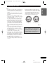
1_CRD3481A_EW_Eng 09-05-2001 08:55 Page 3 Connecting the Units Note: OF O STAR STAR T ACC position F T OF O ESPAÑOL ACC N F ENGLISH • If this unit is installed in a vehicle that does not have an ACC (accessory) position on the ignition switch, the red lead of the unit should be connected to a terminal coupled with ignition switch ON/OFF operations. If this is not done, the vehicle battery may be drained when you are away from the vehicle for several hours. (Fig.
1_CRD3481A_EW_Eng 09-05-2001 08:55 Page 4 Connecting the Units Connecting the Power Cord This Product Light green Used to det This lead m of the park Yellow (video input) (VIDEO INPUT) 15 cm Orange/white To lighting switch terminal. Fuse resistor Red To electric terminal controlled by ignition switch (12 V DC) ON/OFF. Fuse resistor Yellow To terminal always supplied with power regardless of ignition switch position. Fuse holder Black (ground) To vehicle (metal) body.
1_CRD3481A_EW_Eng 09-05-2001 08:55 Page 5 ENGLISH Connection method 1. Clamp the parking brake switch power supply side lead. This Product ESPAÑOL 2. Clamp firmly with needle-nosed pliers. Note: • The position of the parking brake switch depends on the vehicle model. For details, consult the vehicle Owner’s Manual or dealer. DEUTSCH Light green Used to detect the ON/OFF status of the parking brake. This lead must be connected to the power supply side of the parking brake switch.
1_CRD3481A_EW_Eng 09-05-2001 08:55 Page 6 Connecting the Units When Connecting the Multi-Channel AV Master Unit AV cable (supplied with the MultiChannel AV Master Unit) Multi-Channel AV Master Unit (e.g.
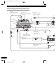
1_CRD3481A_EW_Eng 09-05-2001 08:55 Page 7 ENGLISH Connection box (supplied with the DVD Navigation Unit) Green ESPAÑOL DVD Navigation Unit (e.g. AVIC-9DVD) (sold separately) To video output To audio outputs This product DEUTSCH Voice guidance speaker (supplied) RCA cables (sold separately) 3m 40 cm Black FRANÇAIS Not used. Red DVD player (e.g. SDV-P7) (sold separately) ONE ITALIANO Yellow (front video output) Not used. h Blue 20 pin cable (supplied) Red NEDERLANDS 3m Fig.
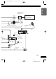
1_CRD3481A_EW_Eng 09-05-2001 08:55 Page 8 Connecting the Units When Connecting the Navigation Unit To audio inputs of car stereo To audio outputs Connection box (supplied with the DVD Navigation Unit) RCA cable (sold separately) DVD Navigation Unit (e.g. AVIC-9DVD) (sold separately) Green To video output RCA cable (sold separately) Voice guidance speaker (supplied) This product 3m Red Yellow (VIDEO INPUT) 15 cm 3m 20 pin cable (supplied) Red Fig.
1_CRD3481A_EW_Eng 09-05-2001 08:55 Page 9 Installation Note: • If installation angle exceeds 30° from horizontal, the unit might not give its optimum performance. (Fig. 5) ENGLISH 30¡ ESPAÑOL • Before finally installing the unit, connect the wiring temporarily, making sure it is all connected up properly, and the unit and the system work properly. • Use only the parts included with the unit to ensure proper installation. The use of unauthorized parts can cause malfunctions.
1_CRD3481A_EW_Eng 09-05-2001 08:55 Page 10 Installation 2. Install side brackets. (Fig. 7) Side bracket Flush surface screw (5 ´ 6 mm) Fig. 7 3. Fastening the unit. (Fig. 8) As a rule, secure with side brackets (large). Holder After inserting the holder into the dashboard, then select the appropriate tabs according to the thickness of the dashboard material and bend them. (Install as firmly as possible using the top and bottom tabs. To secure, bend the tabs 90 degrees.
1_CRD3481A_EW_Eng 09-05-2001 08:55 Page 11 ENGLISH 7 When the installation space is not very deep When installing in a shallow space, secure with side brackets (small). In this case, stick conceal tape on parts that protrude from the dashboard. Dashboard 182 53 ESPAÑOL Holder After inserting the holder into the dashboard, then select the appropriate tabs according to the thickness of the dashboard material and bend them. (Install as firmly as possible using the top and bottom tabs.
1_CRD3481A_EW_Eng 09-05-2001 08:55 Page 12 Installation 2. Fastening the unit to the factory radio mounting bracket. (Fig. 11) (Fig. 12) Select a position where the screw holes of the bracket and the screw holes of this product become aligned (are fitted), and tighten the screws at 2 places on each side. Use any of binding screws (4 ´ 3 mm), binding screws (5 ´ 6 mm) or flush surface screws (5 ´ 6 mm), depending on the shape of the screw holes in the bracket. *1 Use binding screws (4 ´ 3 mm) only.
1_CRD3481A_EW_Eng 09-05-2001 08:55 Page 13 Installing the Voice Guidance Speaker ENGLISH Precaution: • Do not install on the dashboard where it may be subjected to direct sunlight. High temperatures may result in damage to the unit. • Install within the transmission range of the remote control signal. Stick the supplied velcro tape to the back of both the voice guidance speaker and the center console, and attach them.
1_CRD3481A_EW_Eng 09-05-2001 08:55 Page 76 France: tapez 36 15 PIONEER PIONEER CORPORATION 4-1, MEGURO 1-CHOME, MEGURO-KU, TOKYO 153-8654, JAPAN PIONEER ELECTRONICS (USA) INC. P.O. Box 1760, Long Beach, California 90801, U.S.A. TEL: (800) 421-1404 PIONEER EUROPE NV Haven 1087, Keetberglaan 1, B-9120 Melsele, Belgium TEL: (0) 3/570.05.11 PIONEER ELECTRONICS AUSTRALIA PTY. LTD. 178-184 Boundary Road, Braeside, Victoria 3195, Australia TEL: (03) 9586-6300 PIONEER ELECTRONICS OF CANADA, INC.