ORDER NO. CRT3399 DEH-3750MP/XU/GS HIGH POWER CD/MP3/WMA PLAYER WITH FM/AM TUNER DEH-3750MP /XU/GS DEH-3770MP/XU/CS DEH-3750MP/XU/CN This service manual should be used together with the following manual(s): Model No. CX-3158 Order No. CRT3394 Mech.Module S10.1AAC Remarks CD Mech. Module : Circuit Description, Mech. Description, Disassembly For details, refer to "Important Check Points for Good Servicing".
1 2 3 4 SAFETY INFORMATION This service manual is intended for qualified service technicians; it is not meant for the casual do-it-yourselfer. Qualified technicians have the necessary test equipment and tools, and have been trained to properly and safely repair complex products such as those covered by this manual. Improperly performed repairs can adversely affect the safety and reliability of the product and may void the warranty.
5 6 7 8 [Important Check Points for Good Servicing] In this manual, procedures that must be performed during repairs are marked with the below symbol. Please be sure to confirm and follow these procedures. A 1. Product safety Please conform to product regulations (such as safety and radiation regulations), and maintain a safe servicing environment by following the safety instructions described in this manual. 1 Use specified parts for repair. Use genuine parts.
1 2 3 4 CONTENTS SAFETY INFORMATION ..................................................................................................................................... 2 1. SPECIFICATIONS ............................................................................................................................................ 5 2. EXPLODED VIEWS AND PARTS LIST ............................................................................................................ 8 2.1 PACKING ...................
6 7 8 1.
1 2 1 2 3 4 3 4 A B C D E F 6 DEH-3750MP/XU/GS
5 6 7 8 A B C D E F DEH-3750MP/XU/GS 5 6 7 8 7
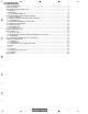
1 2 3 4 2. EXPLODED VIEWS AND PARTS LIST NOTES : • Parts marked by " * " are generally unavailable because they are not in our Master Spare Parts List. • The > mark found on some component parts indicatesthe importance of the safety factor of the part. Therefore, when replacing, be sure to use parts of identical designation. • Screw adjacent to mark on the product are used for disassembly. • For the applying amount of lobricants or glue, follow the instructions in this manual.
5 6 7 8 (1) PACKING SECTION PARTS LIST Mark No. Part No. Mark No. CEA4850 CEA3849 13 14 15 1 2 3 4 5 Accessory Assy Screw Assy ••••• Screw Polyethylene Bag CBA1650 CEG-127 6 7 8 9 10 Screw Screw Polyethylene Bag Handle Bush CRZ50P090FTC TRZ50P080FTC CEG-158 CNC5395 CNV3930 * * Description * 16-1 16-2 16-3 16-4 17 * 11 12 Polyethylene Bag Carton CEG-162 See Contrast table(2) 18 19 20 Description Part No.
1 2 3 4 2.
5 6 7 8 (1) EXTERIOR SECTION PARTS LIST Mark No. > Description Mark No. Part No.
1 2 3 4 (2) CONTRAST TABLE DEH-3750MP/XU/GS, DEH-3770MP/XU/CS and DEH-3750MP/XU/CN are constructed the same except for the following: Mark A B No.
5 6 7 8 A B C D E F DEH-3750MP/XU/GS 5 6 7 8 13
1 2 3 4 2.
5 6 7 8 CD MECHANISM MODULE SECTION PARTS LIST Mark No. Description Mark No. Part No. 1 2 3 4 5 CD Core Unit(S10.
1 2 3 4 3. BLOCK DIAGRAM AND SCHEMATIC DIAGRAM 3.1 BLOCK DIAGRAM A A TUNER AMP UNIT VDD IC 3 EEPROM 5.0V 5V OSC ANTENNA B NC NC NC 18 19 20 21 NC 14 DO 11 NC CK SL DI 10 9 8 CE1 5 ROM_VDD WC CE2 13 IC 5 3.3V ← 7 6 FM/AM TUNER UNIT LPF CN401 AM ANT 1 1 FMRF ATT Rch 2 3 IC 1 3.3V FM ANT ATT FMRF 24 IC 2 2.5V Lch MIXER, IF AMP 23 DET, FM MPX RF adj ANT adj T51 CF52 CF51 DGND AUDIOGND NC 15 22 16 VDD_3.3 OSCGND 12 VCC RFGND 2 ← C E IC 4 3.3V 2.5V 2.
5 6 7 8 A REAR OUTPUT CN352 RESET IC 961 S-80834CNY RST A R Lch VDD 2 Q352 60 RESET 3 TUNPDO 11 TUNPDI 12 TUNPCK 13 TUNPCK 56 TUNPCE1 55 TUNPCE2 CE1 CE2 TUNPDI TUNPDO VDD REGULATOR Q911 VDD B Q912 SYSTEM CONTROLLER IC 601(1/2) PE5460A DALMON 32 BACKUP SENSE BSENS ASENS 64 BSENS 63 ASENS CN901 B.UP FUSE 1 BACK UP 3 3 ACC 2 2 GND 10 10 FL- 12 12 FL+ 9 9 11 11 RLRL+ 6 6 B. REM 1 10A Q931 ACC ACC SENSE B.
1 2 3 4 3.2 OVERALL CONNECTION DIAGRAM(GUIDE PAGE) Note: When ordering service parts, be sure to refer to " EXPLODED VIEWS AND PARTS LIST" or "ELECTRICAL PARTS LIST".
5 6 7 A-b 8 A A TUNER AMP UNIT CEK1286 3A > REAR L CH REAR R CH 332/16 B FM: 29.6dB AM: 19.1dB CD: 36.
C CN901 C D 20 GS,CN 1 2 3 4 5 6 7 8 9 10 11 12 13 14 15 16 17 18 19 20 21 22 23 A-a A-b A A-b B E F A-a asens dsens bsens source AVDD VSS AVREF1 STRKEY1 DISCSENS 471/16 1 2 1 2 DEH-3750MP/XU/GS 3 4 3 4
6 7 FM/AM TUNER UNIT A-a A-b bsrq 1 2 DEH-3750MP/XU/GS 8 The > mark found on some component parts indicates the importance of the safety factor of the part. Therefore, when replacing, be sure to use parts of identical designation. CN1801 B isens STRKEY2 7 *Capacitors Code Practical value 103 0.01uF 101/10 100uF/10V Ex.
A-a A-b 1 CEK1286 3A 22 > TUNER AMP UNIT B FM: 29.6dB AM: 19.1dB CD: 36.
5 6 7 8 10A > CEK1208 A B A-a A-b C D E F A-b 2 1 DEH-3750MP/XU/GS 5 6 7 8 23
1 2 3 4 3.
5 6 7 8 A B KEYBOARD UNIT B C A CN831 40mA,14V D DISPLAY E F D1803,D1804 GS,CN : CL-490SWFSD(12) CS : CL-490S-WF-SD B DEH-3750MP/XU/GS 5 6 7 8 25
1 2 3 4 3.
5 6 7 8 A C-b Decimal points for resistor and capacitor fixed values are expressed as : 2.2 ← 2R2 0.022 ← R022 SWITCHES: CD CORE UNIT(S10.1) S901:HOME SWITCH..........ON-OFF S903:DSCSNS SWITCH......ON-OFF S904:12EJ SWITCH.............ON-OFF S905:8EJ SWITCH...............ON-OFF ras B The underlined indicates the switch position. SIGNAL LINE F T C S ! FOCUS SERVO LINE TRACKING SERVO LINE CARRIAGE SERVO LINE SPINDLE SERVO LINE C CD CORE UNIT(S10.1) 3.
F PICKUP UNIT(P10) (SERVICE) E 28 1 2 3 T # @ C F F 2 T T T T T B F F % C-b F F C-a A-a C-b 1 3 4 A 1 2 D C-a DEH-3750MP/XU/GS 4 T F C S
5 6 C C T T F F 0 9 8 7 $ 4 7 4 5 7 C-a A-a C-b CD DRIVER 5 C S 3 S S F T 6 M2 CXB8933 LOADING /CARRIAGE MOTOR M1 CXC4440 SPINDLE MOTOR 1 2 3 2 C 5 8 A 6 C-b B C D E F C-a DEH-3750MP/XU/GS 8 29 C S S
ras ! C-a C-b C C-b 30 1 2 S C T F B 2 3.3V REGULATOR C CD CORE UNIT(S10.1) SPINDLE SERVO LINE CARRIAGE SERVO LINE TRACKING SERVO LINE FOCUS SERVO LINE SIGNAL LINE The underlined indicates the switch position. SWITCHES: CD CORE UNIT(S10.1) S901:HOME SWITCH..........ON-OFF S903:DSCSNS SWITCH......ON-OFF S904:12EJ SWITCH.............ON-OFF S905:8EJ SWITCH...............ON-OFF Decimal points for resistor and capacitor fixed values are expressed as : 2.2 ←2R2 0.
TYPE_A/D MICRO COMPUTER 2 5 3 6 SRAMLEVEL0 SRAMLEVEL1 SRAMLEVEL2 C-a C-b 3V REGULATOR 6 & ^ 6 A CN721 5 7 4 7 8 A B C D E F 5 6 C-b DEH-3750MP/XU/GS 8 31
1 2 - Waveforms A 1 DSCSNS 2 8SNS 3 12SNS 4 LOEJ B 500ms/div 1 DSCSNS 5 CLCONT 4 LOEJ 6 VD 5V/div 5V/div 5V/div 10V/div 500ms/div 1 DSCSNS 2 8SNS 3 12SNS 4 LOEJ 5V/div 5V/div 5V/div 5V/div 8 cm CD Loading operation Ref.: GND Ref.: GND Ref.
5 0 FIN # FE 6 500mV/div 200ms/div @ TE 500mV/div % RFAGC 7 500mV/div 2ms/div 500mV/div % RFAGC @ TE 9 TIN 8 1V/div 500µs/div 500mV/div 500mV/div Focus Search waveform Track Open waveform 1 Track Jump waveform Ref.: REFO Ref.: REFO Ref.
1 7 SIN 8 CIN 9 TIN A 2 3 1V/div 500ms/div % RFAGC 500mV/div 9 TIN 500mV/div @ TE 0 FIN 1V/div 1V/div 1V/div 1V/div CD-ROM >> CD-DA mode change(Band key) Black dot(800µm) during play Ref.: REFO Ref.
5 6 7 8 A B C D E F DEH-3750MP/XU/GS 5 6 7 8 35
1 2 3 4 4. PCB CONNECTION DIAGRAM 4.1 TUNER AMP UNIT A NOTE FOR PCB DIAGRAMS 1.The parts mounted on this PCB include all necessary parts for several destination. For further information for respective destinations, be sure to check with the schematic diagram. 2.Viewpoint of PCB diagrams A TUNER AMP UNIT CORD ASSY 1 Capacitor Connector 2 1 3 5 7 9 11 13 15 3 2 4 6 8 10 12 14 16 SIDE A B Chip Part P.C.
5 6 7 8 A SIDE A REAR OUTPUT SSY 11 13 15 1 2 0 12 14 16 3 4 ANTENNA RCA B 2 1 FM/AM TUNER UNIT C D E B CN1801 F FRONT A DEH-3750MP/XU/GS 5 6 7 8 37
1 A A 2 3 4 TUNER AMP UNIT 1 B 1 C D TEST E F A 38 DEH-3750MP/XU/GS 1 2 3 4 PCL
5 6 7 8 A SIDE B 1 1 B C D EST PCL E F A DEH-3750MP/XU/GS 5 6 7 8 39
F VOLUME E SOURCE 1 2 3 4 5 6 40 1 2 LOCAL/BSM DOWN LOUDNESS RIGHT DISPLAY AUDIO KEYBOARD UNIT 2 LCD1801 BAND LEFT B UP EJECT A EQ CLOCK 1 3 3 4 4.
5 B 6 7 KEYBOARD UNIT 8 SIDE B A B C D A CN831 E F B DEH-3750MP/XU/GS 5 6 7 8 41
1 2 3 4 4.3 CD CORE UNIT(S10.1) C CD CORE UNIT(S10.
5 C 6 7 CD CORE UNIT(S10.
1 2 3 4 5. ELECTRICAL PARTS LIST A NOTE: • Parts whose parts numbers are omitted are subject to being not supplied. • The part numbers shown below indicate chip components. Chip Resistor RS1/_S___J,RS1/__S___J Chip Capacitor (except for CQS.....) CKS....., CCS....., CSZS..... • The > mark found on some component parts indicatesthe importance of the safety factor of the part. Therefore, when replacing, be sure to use parts of identical designation. Circuit Symbol and No. B Circuit Symbol and No.
5 Circuit Symbol and No. 6 7 Part No. Circuit Symbol and No.
1 2 Circuit Symbol and No. C 991 C 992 C 994 A (B,20,50) (A,26,60) (A,30,34) 470µF/16V 3 Part No. Circuit Symbol and No.
5 Circuit Symbol and No. 6 7 Part No.
1 2 3 4 6. ADJUSTMENT 6.1 CD ADJUSTMENT A 1) Cautions on adjustments • In this product the single voltage (3.3V) is used for the regulator. The reference voltage is the REFO1 (1.65V) instead of the GND. If you should mistakenly short the REFO1 with the GND during adjustment, accurate voltage will not be obtained, and the servo’s misoperation will apply excessive shock to the pickup. To avoid such problems: a. Do not mix up the REFO1 with the GND when connecting the (-) probe of measuring instruments.
5 6 7 8 - Flow Chart [4]+[6]+Reset or [4]+[6]+BU+ACC [KEY] Contents A Test Mode In Display [CD]or[SOURCE] Source On TRK SEC MIN [BAND] [3] Power On Power On [2] (T.Offset is adjusted) [4] (T.
1 2 3 4 6.2 CHECKING THE GRATING AFTER CHANGING THE PICKUP UNIT A • Note : The grating angle of the PU unit cannot be adjusted after the PU unit is changed. The PU unit in the CD mechanism module is adjusted on the production line to match the CD mechanism module and is thus the best adjusted PU unit for the CD mechanism module. Changing the PU unit is thus best considered as a last resort. However, if the PU unit must be changed, the grating should be checked using the procedure below.
5 6 7 8 Ech → Xch 20mV/div, AC Fch → Ych 20mV/div, AC Grating waveform A 0° 30° B 45° 60° C D 75° 90° E F DEH-3750MP/XU/GS 5 6 7 8 51
1 2 3 4 6.3 ERROR MODE - Error Messages Error is displayed with number for Error cause when CD is inoperative or stops with Error during operation. The purpose is to reduce nonsense calls from users as well as to assist all related analysis and repair for defects at service station. A (1) Basic Display Method 1) When CSMOD (CD mode area for system) is SERRORM, Error code will be written in DMIN (minutes area for display), DSEC (seconds area for display).
5 6 7 8 6.4 SYSTEM MICROCOMPUTER TEST PROGRAM A - PCL Output In the normal operation mode (with the detachable panel installed, the ACC switched ON, the standby mode cancelled), shift the TESTIN (Pin 15) terminal to H. The clock signal is output from the PCL terminal (Pin 14). The frequency of the clock signal is 786.432kHz that is one 16th of the fundamental frequency. The clock signal should be 786.432kHz ± 31.5Hz.
1 2 3 4 7. GENERAL INFORMATION 7.1 DIAGNOSIS A 7.1.1 DISASSEMBLY - Removing the Case (not shown) 1. Remove the Case. CD Mechanism Module - Removing the CD Mechanism Module (Fig.1) 1 Remove the four screws. B 1 Disconnect the connector and then remove the CD Mechanism Module. 1 - Removing the Grille Assy (Fig.1) 2 Release the two latchs and then remove the Grille Assy. 1 C 2 2 1 Fig.1 Grille Assy - Removing the Tuner Amp Unit (Fig.2) 1 Remove the screw.
5 6 7 8 - How to hold the Mechanism Unit 1. Hold the top and bottom frame. 2. Do not squeeze top frame's front portion too tight, because it is fragile. A B Do not squeeze. - Removing the Upper and Lower Frames 1. With a disc clamped, remove the four springs (A), the two springs (B), the two springs (C), and the four screws. 2. To remove the upper frame, open it on the fulcrum A. 3. While lifting the carriage mechanism, remove the three dampers. 4.
1 2 3 4 - Removing the Pickup Unit 1. Apply shorting solder to the Pickup flexible cable. Disconnect the cable. 2. Set the mechanism to the clamp mode. 3. Remove the lead wires from the inner holder. 4. Remove the washer, styling holder, change arm, and pickup lock arm. 5. While releasing from the hook of the inner holder, lift the end of the feed screw. Caution: In assembling, move the planet gear to the load/eject position before setting the feed screw in the inner holder.
5 6 7 8 7.1.2 CONNECTOR FUNCTION DESCRIPTION A 16 14 12 10 8 6 4 2 15 13 11 9 7 5 3 1 10A B ANTENNA JACK REAR OUTPUT Pin No. 1 2 3 4 5 6 7 8 B.UP GND ACC NC NC B.REM NC NC Pin No.
1 2 3 4 7.2 PARTS 7.2.1 IC - Pin Functions(PE5460A) A Pin No.
5 Pin No. 63 64 65 66 67 68 69, 70 71 72 73 74 75 76 77 78 79 80 6 I I I I I * PE5460A A B IC's marked by * are MOS type. Be careful in handling them because they are very liable to be damaged by electrostatic induction.
1 2 3 4 3 4 - Pin Functions(PD6340A) Pin No.
5 6 7 8 - Pin Functions(UPD63763GJ) Pin No. 1 2 3 4-8 9-16 17 18 19 20 21 22 23, 24 25 26 27 28 29 30 31 32 33 34 35 36 37 38 39-41 42 43 44 45 46 47 48 49 50 51 52 53 54 55 56 57 58 59 60 61 62 63 64 65 66 67 68 69 70 71 72 73-88 89-99 Pin Name D.VDD D1.GND reset AB12-8 AD7-0 cs ASTB read write wait INTQ IFMODE0, 1 D1.VDD DA.VDD ROUT DA.GND REGC DA.GND LOUT DA.VDD X.VDD XTAL xtal X.GND VDDREG15 PWMSW0 TEST3-1 PWMSW1 TESTEN D1.GND DIN DOUT SCKIN SCKO LRCKIN LRCK xtalen D1.
1 2 Pin No. 100 101 102 103 104 105 106 107 108 109 110 111 112 113 114 115 116 117 118 119 120, 121 122 123 124 125 126 127 128 129 130 131 132 133 134 135 136 137 138 139 140 141 142 143 144 A B C D Pin Name D.VDD FD+ FDTD+ TDSD+ SDMD+ MDREFOUTSV AD.VDD EFM ASY ATEST RFI AD.GND AGCO C3T AGCI RFO EQ2, 1 RF2RFA.GND A C B D F E VREFIN A.VDD REFOUT REFC FEFEO ADIN TETEO TE2 TEC LD PD D.
5 6 7 8 - Pin Functions(PE5454A) Pin No.
1 Pin No.
5 6 7 8 - FM/AM Tuner Unit 1 NC NC NC 18 19 20 21 NC DO 14 NC DI CK SL 5V OSC 11 A IC 3 EEPROM 5.0V AM ANT 10 9 8 CE1 5 ROM_VDD CE2 WC 13 IC 5 3.3V ← 7 6 LPF FMRF ATT Rch 3 IC 1 3.3V FM ANT ATT FMRF ANT adj 24 IC 2 2.5V Lch MIXER, IF AMP 23 DET, FM MPX B RF adj T51 CF52 No.
1 2 3 4 3 4 7.2.
5 6 7 8 7.3 OPERATIONAL FLOW CHART A Power ON AVREF1, VDD, AVDD=5V Pin 7, 68, 74, 75 B bsens Pin 64 bsens=L asens Pin 63 C asens=L Starts communication with Grille microcomputer. 300ms swvdd←L Pin 21 300ms D In case of the above signal, the communication with Grille microcomputer may fail. If the time interval is not 300msec, the oscillator may be defective. Source keys operative Source ON E SYSPW←H Pin 43 Completes power-on operation.(After that, proceed to each source operation.
1 2 3 4 3 4 7.
5 6 7 8 8.
1 2 1 2 3 4 3 4 A B C D E F 70 DEH-3750MP/XU/GS
5 6 7 8 A B C D E F DEH-3750MP/XU/GS 5 6 7 8 71
1 2 1 2 3 4 3 4 A B C D E F 72 DEH-3750MP/XU/GS
5 6 7 8 A B C About the fixing screws for the front panel If you do not operate the Detaching and Replacing the Front Panel Function, use the supplied fixing screws and fix the front panel to this unit.
1 E 2 3 Green/black Violet/black ≠ ≠ With a 2 speaker system, do not connect anything to the speaker leads that are not connected to speakers. Rear speaker + Violet + Green Gray/black ≠ White/black ≠ Gray + White ≠ + + ≠ + System remote control Rear speaker Right Front speaker Perform these connections when using the optional amplifier. Rear speaker 2 Black (ground) To vehicle (metal) body.
5 6 7 8 A B C D E F DEH-3750MP/XU/GS 5 6 7 8 75
1 2 3 4 - Jigs List Name Test Disc L.P.F. A Jig No.