DJ MIXER DJM-1000 Operating Instructions
Thank you for buying this Pioneer product. Please read through these operating instructions so you will know how to operate your model properly. After you have finished reading the instructions, put them away in a safe place for future reference. In some countries or regions, the shape of the power plug and power outlet may sometimes differ from that shown in the explanatory K015 En drawings. However the method of connecting and operating the unit is the same.
FEATURES 1 High sound quality design Analog signals are transmitted via the shortest path and converted to digital signals by a 96 kHz sampling, 24 bit, high-quality A/D converter, thus passing the signals to the digital mixing stage under optimum conditions. Through the use of a 32 bit DSP, mixing is achieved with zero sound quality degradation, and together with simultaneous ideal filtering, optimum sound is produced for professional DJs working in clubs.
CAUTIONS REGARDING HANDLING Location Install the unit in a well-ventilated location where it will not be exposed to high temperatures or humidity. ÷ Do not install the unit in a location which is exposed to direct rays of the sun, or near stoves or radiators. Excessive heat can adversely affect the cabinet and internal components. Installation of the unit in a damp or dusty environment may also result in a malfunction or accident. (Avoid installation near cookers etc.
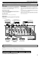
BEFORE USING (CONNECTIONS) CONNECTIONS CONNECTION PANEL 1 2 3 4 5 6 7 8 9 OUTPUT 3 2 HOT OFF INPUT SIGNAL GND. COLD MASTER ATT. 0dB 1 GND –3dB 6 –6dB –12dB POWER 10 MASTER 2 PHONO CD / LINE SIGNAL GND. 5 PHONO CD / LINE 4 PHONO CD / LINE SIGNAL GND.
BEFORE USING (CONNECTIONS) Before making or changing connections, switch off the power and disconnect the power cord from the AC outlet. POWER CORD CONNECTION Connect the power cord last. ÷ When all other connections are completed, connect the supplied power cord to the AC inlet located on the rear panel of this unit, and connect the power plug to an AC outlet or auxiliary power socket on an amplifier. ÷ Be sure to use only the supplied power cord.
BEFORE USING (CONNECTIONS) CONNECTING TO THE EFFECTOR AND OUTPUT CONNECTORS Master output External effector There is an XLR plug correspondent balanced output MASTER 1, and a RCA plug correspondent unbalanced output MASTER 2. Set the output level using the MASTER ATT. dial to match the input sensitivity of the connected power amplifier. Use a cable with Ø6.3 mm phone plugs to connect the DJ mixer’s SEND connectors to the input connectors of an external effector.
BEFORE USING (CONNECTIONS) CONNECTING MICROPHONES, HEADPHONES Headphones Sub microphone Headphones with Ø6.3 mm stereo phone plugs can be connected to the PHONES plug in the operation panel (top panel). A Ø6.3 mm phone plug microphone can be connected to the SUBMIC input connectors on channel 5 and channel 6 of the DJM1000. Switch the input selector switch of the connected channel to [SUBMIC]. Main microphone A microphone with either a Ø6.
BEFORE USING (PART NAMES AND FUNCTIONS) PART NAMES AND FUNCTIONS Operation Panel 1 7 LINK 9 10 11 12 28 29 MIC CD/LINE LINE PHONO SOUND 1 VISUAL 44 8 V CD/LINE LINE PHONO SOUND 2 CD/LINE LINE PHONO DIGITAL CD/LINE LINE PHONO DIGITAL CD/LINE SUBMIC PHONO DIGITAL HI CD/LINE SUBMIC PHONO DIGITAL ISOLATOR ON 30 SOUND 1 S1 45 2 SOUND 2 MIC LEVEL S2 13 TRIM OVER 13 TRIM OVER 13 TRIM OVER 13 TRIM OVER 13 TRIM OVER 13 TRIM OVER MASTER LEVEL EFX 1 46 10 EFX 2 FADER
BEFORE USING (PART NAMES AND FUNCTIONS) 8. Channel 2 input selector switch SOUND 2: Dedicated input for DJ CD players supporting digital link (mini DIN connector). LINE: Phone type connector (when a monaural signal is connected to only the L channel, the signal is input to both L and R channels). CD/LINE: RCA type connector with line level input. PHONO: RCA type connector with phono level input. 9. Channel 3 input selector switch DIGITAL: RCA type connector with coaxial cable digital input.
BEFORE USING (PART NAMES AND FUNCTIONS) 24. Cross fader assign B indicator (B) Lights green when power is ON. 25. Channel fader slider Adjusts volume of each channel. (Adjustable range: –∞ to 0 dB) Outputs according to the channel fader curve set by the CURVE ADJUST dial (CH FADER). Master output control section 26. MASTER fader slider Headphone output section 36.
BEFORE USING (PART NAMES AND FUNCTIONS) 46. Effector LINK buttons 1, 2 (EFX 1, 2)/Indicator (E 1, 2) [AUX type] Input When a digital link cable (mini DIN connector) is used to connect this unit to a PIONEER DJ effector with digital link support (EFX-1000), setting these buttons to ON enables fader effect functions. The indicator lights when the function is turned ON. EQ CH FADER SEND RETURN Fader start/stop ON/OFF section 47.
OPERATIONS OPERATIONS [Headphones output] BASIC OPERATIONS 1. Choose the source with the headphone CUE button (channel 1-6, MASTER, RETURN 1, RETURN 2). Booth monitor output Main microphone input ÷ The chosen headphone CUE button will light brightly. 2. Use the HEADPHONES selector switch (MONO SPLIT/ STEREO) to select the format of the audio output. 1 2 7 3 4 –26 +6 5 8 6 Fader curve Headphone output 1. Set the POWER switch located on the rear panel (connection panel) to ON. 2.
OPERATIONS [Starting playback with cross fader] FADER START FUNCTION 1 Press the FADER START button for the channel (CH-1 to CH-6) connected to the CD player you wish to control. By using a control cable to connect the unit to an optional PIONEER CD player, playback on the CD player can be started using the channel fader or cross fader functions (if a digital link connection is made, use of the control cable is unnecessary).
OPERATIONS DIGITAL LINK FUNCTION Link system diagram DJ effecter supporting digital link AV mixer supporting digital link Fad e (EF r effe X li c nk) t link EFX-1000 Vis Aud io s BPM (So link und Lin k EFX 1 (2) ign ( al –26 ign orp ua Vis hin l Li SOUND 1 g nk) +6 Fad t DJ CD player supporting tar er s digital link d a F A VISUAL DJM-1000 ) os udi m ual SOUND 2 Au al dio er s sig tar t DJ CD player supporting digital link nal BPM (So link und Lin k) link nk) BPM nd Li
OTHER (TROUBLESHOOTING) TROUBLESHOOTING Incorrect operations are often mistaken for trouble and malfunctions. If you think there is something wrong with this component, check the points below. Sometimes the trouble may originate from another component. Thus, also check the other electrical appliances also in use. If the trouble cannot be rectified even after checking the following items, contact your dealer or nearest PIONEER service center. Symptom Possible Cause Countermeasure Power does not turn on.
OTHER (SPECIFICATIONS) SPECIFICATIONS 1. General Specifications 3. Input output connectors Power supply voltage ............................................... AC 120 V, 60 Hz Power consumption .................................................................... 63 W Operating temperature ................... +5 ˚C to +35˚C (+41 ˚F to +95˚F) Operating humidity ......................... 5 % to 85 % (no condensation) Weight ................................................................. 12.
OTHER (BLOCK DIAGRAM) BLOCK DIAGRAM DSP MIC LEVEL MIC AMP MIC A/D MIC DUAL PORT RAM BUS -COM PHONO AMP CH1 PHONO TRIM BUF. MIC A/D LINE/CD D/A HP CH1 PHONES MUTE BUF. CH2 LINE DIR SOUND MASTER1 ATT CH3 SRC CH2 same as CH1 PHONO AMP CH3 D/A MASTER CH4 MUTE MASTER2 MUTE CH5 BOOTH D/A CH6 REC D/A BOOTH MUTE REC MUTE PHONO DIT TRIM BUF. DIGITAL OUT A/D LINE/CD BUF.
We Want You Listening For A Lifetime Selecting fine audio equipment such as the unit you’ve just purchased is only the start of your musical enjoyment. Now it’s time to consider how you can maximize the fun and excitement your equipment offers. This manufacturer and the Electronic Industries Association’s Consumer Electronics Group want you to get the most out of your equipment by playing it at a safe level.