DJM-850-K DJM-850-S DJM-850-W DJ MIXER TABLE DE MIXAGE DJ-MISCHPULT http://pioneerdj.com/support/ The Pioneer website shown above offers FAQs, information on software and various other types of information and services to allow you to use your product in greater comfort. Le site Pioneer ci-dessus offre une FAQ, des informations sur le logiciel et divers types d’informations et de services permettant de tirer le meilleur parti de ce produit.
Thank you for buying this Pioneer product. Please read through these operating instructions so you will know how to operate your model properly. After you have finished reading the instructions, put them away in a safe place for future reference. In some countries or regions, the shape of the power plug and power outlet may sometimes differ from that shown in the explanatory drawings. However the method of connecting and operating the unit is the same.
VENTILATION CAUTION When installing this unit, make sure to leave space around the unit for ventilation to improve heat radiation (at least 5 cm at rear, and 3 cm at each side). WARNING Slots and openings in the cabinet are provided for ventilation to ensure reliable operation of the product, and to protect it from overheating.
Contents How to read this manual The names of displays, menus, and buttons in this manual are enclosed in brackets. (e.g. [MASTER] channel, [ON/OFF], [File] menu) Before start Features........................................................................................................ 5 What’s in the box......................................................................................... 5 Connections Rear panel........................................................................................
English Before start Features This unit is a 4-channel DJ mixer carrying over the technology of the Pioneer DJM series, the world standard for club sound. It is not only equipped with a variety of functions for DJ performances, including USB sound card, BEAT COLOR FX, SOUND COLOR FX and BEAT EFFECT, it also uses a high sound quality, high reliability design and a panel layout with high operability to provide powerful support for all DJ performances.
Connections Be sure to turn off the power and unplug the power cord from the power outlet whenever making or changing connections. Refer to the operating instructions for the component to be connected. Connect the power cord after all the connections between devices have been completed. Be sure to use the included power cord.
! When creating a DVS (Digital Vinyl System) combining a computer, audio interface, etc., be careful in connecting the audio interface to this unit’s input terminals and in the settings of the input selector switches. Also refer to the operating instructions of the DJ software and audio interface. Analog player Cassette deck, CD player, etc.
Connecting to the control panel About the driver software and setting utility software Be sure to connect using the included USB cable. The driver software is required to input and output the sound of a computer using this unit’s built-in USB sound card. Prepare a computer on which a Windows or Mac operating system is installed and the proprietary driver software provided by Pioneer. When the driver software is installed, the settings utility software is installed at the same time.
4 Damages and remedies for breach You agree that any breach of this Agreement’s restrictions would cause Pioneer irreparable harm for which money damages alone would be inadequate. In addition to damages and any other remedies to which Pioneer may be entitled, You agree that Pioneer may seek injunctive relief to prevent the actual, threatened or continued breach of this Agreement. 5 Termination Pioneer may terminate this Agreement at any time upon Your breach of any provision.
! When the installation of the driver software is completed, you need to reboot your computer. About the installation procedure (Mac OS X) Read Cautions on Installation carefully before installing the driver software. ! To install or uninstall the driver software, you need to be authorized by the administrator of your computer. Have the name and password of the administrator of your computer ready in advance. 1 Insert the included CD-ROM into the computer’s CD drive. The CD-ROM folder appears.
Click the [ASIO] tab. English Setting the audio data output from this unit to the computer Display the setting utility before starting. 1 Click the [MIXER OUTPUT] tab. ! 2 Click the [Mixer Audio Output] pull-down menu. Select and set the audio data to be output to the computer from the flow of audio signals inside this unit.
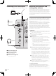
Operation POWER MIC a USB MIC1 CD/LINE a PHONO USB 1/2 CD/LINE a LINE USB 3/4 b LEVEL MIC 2 0 3 12 OFF 12 4 dB 1 1 1 0 -26 / 0 -26 / 0 -26 / 0 6 MID -5 6 -7 LOW -5 -26 / 6 -7 LOW -10 -5 -26 / 6 -7 LOW -10 -10 -15 -15 -15 -24 -24 -24 -26 / 6 dB f BEAT -26 / 6 COLOR dB f BEAT -26 / 6 FILTER e LOW L COLOR 2 3 LOW g CUE FADER START e HI LOW g CUE w BEAT dB R AUTO / TAP LOW g y g g CUE R FILTER FLANGER TRANS PHASER CUE REV
Adjusts the sound level output from the [MIC1] channel. 2 MIC2 LEVEL control (page 15) Adjusts the sound level output from the [MIC2] channel. 3 EQ (HI, LOW) controls (page 15) These adjust the tone quality of the [MIC1] and [MIC2] channels. 4 OFF, ON, TALK OVER selector switch (page 15) Turns the microphone on/off. 5 SOUND COLOR FX buttons (page 16) These turn the SOUND COLOR FX effects on/off. 6 FADER START (1, 2, 3, 4) buttons (page 14) These turn the fader start function on/off.
Basic Operation Outputting sound 1 Press [POWER] button. Turns on the power of this unit. 2 Switch the [CD/LINE, PHONO, LINE, USB */*] selector switch. Selects the input sources for the different channels from among the devices connected to this unit. — [PHONO]: Selects the analog player connected to the [PHONO] terminals. — [CD/LINE], [LINE]: Selects the DJ player or cassette deck connected to the [CD/LINE] or [LINE] terminals. — [USB */*]: Selects the sound of the computer connected to the [USB] port.
! 1 Set the [CROSS FADER ASSIGN (A, THRU, B)] selector switch to [A] or [B]. 1 Set the [MONO, STEREO] selector switch to [STEREO]. 2 Press one of the [FADER START (1, 2, 3, 4)] buttons. Select the channel to be started with the fader start function. 3 Set the crossfader. Set to the edge opposite the side on which the channel you want to use with the fader start function is set. 4 Set the cue on the DJ player. The DJ player pauses playback at the cue point. 5 Set the crossfader.
6 Parameter display section This displays the parameters specified for the individual effects. When the [BEAT c, d] button is pressed, the corresponding beat fraction is displayed for 1 second. When a value outside the parameter range is specified with the [BEAT c, d] button, the value does not change and the display flashes. These effects change in association with the [COLOR] controls for the different channels. 7 % (ms) These light according to the units for the different effects.
1 Connect this unit and external effector. For instructions on connections, see Connecting output terminals on page 7. 2 Turn the [DELAY, ECHO, UP ECHO, SPIRAL, REVERB, TRANS, FILTER, FLANGER, PHASER, ROBOT, SLIP ROLL, ROLL, REV ROLL, SND/RTN] selector switch. Select [SND/RTN]. 3 Turn the [1, 2, 3, 4, MIC, CF.A, CF.B, MASTER] selector switch. This selects the channel to which the effect is applied. 4 Press the [ON/OFF] button for [BEAT EFFECTS].
Types of effects BEAT COLOR FX/SOUND COLOR FX effect types Effect Name [BEAT] button status Descriptions [COLOR] control Off White noise generated inside this unit is mixed in to the sound of the channel via the filter and output. ! The volume can be adjusted by turning the [TRIM] controls for the respective channels. The sound quality can be adjusted by turning the [EQ/ISO (HI, MID, LOW)] controls.
This function adds a reverberation effect to the input sound. When the delay time is changed, the pitch changes simultaneously. Input sound turned off Fade-out BEAT c, d buttons (parameter 1) Use these to set the cycle for moving the cut-off frequency as a time of 1/4 – 64/1 with respect to the time of one beat of the BPM. TIME control (parameter 2) Use this to set the cycle at which the cut-off frequency is moved.
SLIP ROLL1 2 SND/RTN1 The sound being input at the point when the [ON/OFF] is pressed is recorded, and the recorded sound is output repeatedly according to the beat fraction set with the [BEAT c, d] buttons. When the effect time changes, the input sound is recorded again. Connect an external effector, etc., here.
! ! “CC” is the abbreviation of “control change”. A control change is a type of MIDI signal used to transmit various types of control information, such as timbre, volume, etc. On this unit, values from 0 to 127 are output as CC mainly when controls and faders are operated. CC are also output when certain buttons are operated. “Note” is a MIDI term used when pressing or releasing notes on a piano or other keyboard.
Category SW Name SOUND COLOR FX Fader Start HEADPHONES Fader Start MIDI Trigger/Toggle Transmitted data CC 042 2 OFF=0, ON=127 ECHO Switch CC 055 2 OFF=0, ON=127 UP ECHO Switch CC 061 2 OFF=0, ON=127 SPIRAL Switch CC 043 2 OFF=0, ON=127 REVERB Switch CC 054 2 OFF=0, ON=127 TRANS Switch CC 053 2 OFF=0, ON=127 FILTER Switch CC 059 2 OFF=0, ON=127 FLANGER Switch CC 050 2 OFF=0, ON=127 PHASER Switch CC 057 2 OFF=0, ON=127 ROBOT Switch CC 051 2 OFF=0, ON=12
English Changing the settings 1 Press the [MIDI] [SETUP (WAKE UP)] button for at least 1 second. The [USER SETUP] screen is displayed. ! To display the [CLUB SETUP] screen, first turn the unit’s power off, then press the [POWER] button while pressing the [MIDI] [SETUP (WAKE UP)] button. 2 Press the [BEAT c, d] button. Select the setting item. 3 Press the [TAP] button. The screen switches to the setting item’s setting value change screen.
Additional information Troubleshooting ! ! Incorrect operation is often mistaken for trouble or malfunction. If you think that there is something wrong with this component, check the points below. Sometimes the trouble may lie in another component. Inspect the other components and electrical appliances being used. If the trouble cannot be rectified after checking the items below, ask your nearest Pioneer authorized service center or your dealer to carry out repair work.
Check Remedy Effect sound cannot be monitored even when the [CUE] button for [BEAT EFFECTS] is pressed. — The circuit generating the [ECHO], [UP ECHO], [SPIRAL], [REVERB], [ROLL], [SLIP ROLL] and [REV ROLL] echo sounds is positioned after the effect circuit, so the effect sound cannot be monitored. This is not a malfunction. Sound is distorted when an analog player is connected to this unit’s [PHONO] terminals.
Block Diagram MIC1 MIC1 LEVEL ADC MIC2 LEVEL MIC2 DIGITAL MASTER CH1 CD/LINE FPGA DIT ADC PHONO CH2 CD/LINE CH1_Analog PHONES CH2_Analog MASTER CH2_ASEL_OUT DAC CH3 CD/LINE MUTE MASTER 1 BOOTH CH3_Analog MUTE MASTER 2 MUTE BOOTH MUTE REC MUTE SEND ADC LINE D SP CH4_Analog REC CH3_ASEL_OUT CD/LINE CH4 PHONES MUTE ADC LINE MUTE DAC Digital MASTER MIC CH1_ASEL_OUT SEND RETURN DAC ADC PHONO CH1_USB1/2 USB1/2 CH2_USB3/4 USB3/4 CH3_USB5/6 USB5/6 CH4_USB7/
! ! ! ! Pioneer and rekordbox are trademarks or registered trademarks of the PIONEER CORPORATION. Microsoft®, Windows® 7, Windows Vista®, Windows® XP, and Windows® are either registered trademarks or trademarks of Microsoft Corporation in the United States and/or other countries. Apple, Macintosh and Mac OS are trademarks of Apple Inc., registered in the U.S. and other countries. ASIO is a trademark of Steinberg Media Technologies GmbH. Specifications General Power requirements...........................
Nous vous remercions d’avoir acquis un produit Pioneer. Veuillez lire attentivement ce mode d’emploi afin de connaître la manière d’utiliser l’appareil comme il convient. Cela fait, conservez le mode d’emploi de façon à pouvoir vous y référer en cas de nécessité. Dans certains pays ou certaines régions, la forme de la fiche et de la prise d’alimentation est un peu différente de ce qui est montré dans les illustrations. Toutefois, l’appareil se raccorde et fonctionne de la même façon.
PRÉCAUTION DE VENTILATION Lors de l’installation de l’appareil, veillez à laisser un espace suffisant autour de ses parois de manière à améliorer la dissipation de chaleur (au moins 5 cm à l’arrière et 3 cm de chaque côté). AVERTISSEMENT Les fentes et ouvertures du coffret sont prévues pour la ventilation, pour assurer un fonctionnement stable de l’appareil et pour éviter sa surchauffe.
Sommaire Comment lire ce manuel Les noms d’écrans, de menus et de touches sont entre crochets dans ce manuel. (ex. canal [MASTER], menu [ON/OFF], [File]) Informations préliminaires Caractéristiques........................................................................................... 5 Contenu du carton d’emballage................................................................ 5 Raccordements Panneau arrière...........................................................................................
Informations préliminaires DISPOSITION STANDARD Cet appareil est une table de mixage DJ à 4 canaux intégrant la technologie spécifique des DJM Pioneer, la référence mondiale pour les discothèques. Il présente non seulement une grande variété de fonctionnalités pour le DJing, entre autres la carte son USB, BEAT COLOR FX, SOUND COLOR FX et BEAT EFFECT, mais aussi une haute qualité sonore, une conception extrêmement fiable et une disposition des boutons, curseurs, etc.
Raccordements Veillez à toujours éteindre les appareils et à débrancher le cordon d’alimentation de la prise secteur avant de raccorder un appareil ou de changer les liaisons. Reportez-vous au mode d’emploi de l’appareil devant être raccordé. Lorsque tous les appareils ont été raccordés, vous pouvez brancher le cordon d’alimentation. Veillez à utiliser le cordon d’alimentation fourni.
Raccordement des prises d’entrée ! Lorsque vous établissez un DVS (Système Vinyle Numérique) comprenant un ordinateur, une interface audio, etc., faites attention au raccordement de l’interface audio aux prises d’entrée de cet appareil et aux réglages des sélecteurs d’entrée. Reportez-vous aussi au mode d’emploi du logiciel DJ et de l’interface audio.
Raccordement au panneau de commande À propos du pilote et de l’utilitaire de réglage Veillez à utiliser le câble USB fourni pour le raccordement. Ordinateurs Le logiciel est nécessaire pour que le son d’un ordinateur puisse être reçu et transmis par la carte son USB de cet appareil. Installez le logiciel fourni par Pioneer sur un ordinateur Windows ou Mac. Lorsque le logiciel est installé, l’utilitaire de paramétrage est également installé.
3 Exclusion de garantie 4 Dommages-intérêts et recours pour infraction Vous acceptez que toute infraction aux restrictions de cet accord causerait à Pioneer un mal irréparable pour lequel des dommages-intérêts seuls seraient inadéquats. En plus des dommages-intérêts et autres recours auxquels Pioneer peut avoir droit, vous acceptez que Pioneer puisse saisir la justice pour empêcher toute infraction ou tout risque d’infraction ou pour faire cesser toute infraction à cet accord.
! Lorsque l’installation du pilote est terminée, vous devez redémarrer votre ordinateur. ! À propos de l’installation (Mac OS X) Lisez attentivement Précautions à prendre lors de l’installation avant d’installer le pilote. ! Pour installer ou désinstaller le pilote, vous devez avoir l’autorisation de l’administrateur de votre ordinateur. Ayez à disposition le nom et le mot de passe de l’administrateur de votre ordinateur. 1 Insérez le CD-ROM inclus dans le lecteur CD de l’ordinateur.
Réglage de la sortie des données audio de cet appareil vers l’ordinateur Réglage de la taille de la mémoire (lorsque ASIO de Windows est utilisé) Affichez l’utilitaire de réglage avant de commencer. Si une application utilisant cet appareil comme appareil audio par défaut (logiciel DJ, etc.) est ouverte, fermez-la avant de régler la taille de la mémoire. Affichez l’utilitaire de réglage avant de commencer. 1 Cliquez sur l’onglet [MIXER OUTPUT]. Cliquez sur l’onglet [ASIO].
Fonctionnement POWER MIC a USB MIC1 CD/LINE a PHONO USB 1/2 CD/LINE a LINE USB 3/4 b LEVEL MIC 2 0 3 12 OFF 12 4 dB 1 1 1 0 -26 / 0 -26 / 0 -26 / 0 6 MID -5 6 -7 LOW -5 -26 / 6 -7 LOW -10 -5 -26 / 6 -7 LOW -10 -10 -15 -15 -15 -24 -24 -24 -26 / 6 dB f BEAT -26 / 6 COLOR dB f BEAT -26 / 6 FILTER e LOW L COLOR 2 3 LOW g CUE FADER START e HI LOW g CUE w BEAT dB R AUTO / TAP LOW g y g g CUE R FILTER FLANGER TRANS PHASER CUE
1 Commande MIC1 LEVEL (la page 15) Ajuste le niveau du son provenant du canal [MIC1]. 2 Commande MIC2 LEVEL (la page 15) Ajuste le niveau du son provenant du canal [MIC2]. 3 Commandes EQ (HI, LOW) (la page 15) Ajustent la qualité du timbre des canaux [MIC1] et [MIC2]. Allume/éteint le microphone. 5 Touches SOUND COLOR FX (la page 16) Mettent en ou hors service les effets SOUND COLOR FX. 6 Touches FADER START (1, 2, 3, 4) (la page 14) Mettent en/hors service la fonction de lancement par le fader.
Opérations de base Contrôle du son par un casque 1 Raccordez le casque à la prise [PHONES]. Restitution du son 1 Appuyez sur la touche [POWER]. Allumez cet appareil. 2 Commutez le sélecteur [CD/LINE, PHONO, LINE, USB */*]. Sélectionnez parmi les dispositifs raccordés à cet appareil les sources d’entrée prévues pour les différents canaux. — [PHONO] : Sélectionne le lecteur analogique raccordé aux prises [PHONO].
Lancer la lecture en utilisant le fader de canal Réglage de la qualité du son 1 Réglez le sélecteur [CROSS FADER ASSIGN (A, THRU, B)] sur [THRU]. Tournez les commandes [EQ (HI, LOW)] des canaux [MIC]. 2 Appuyez sur une des touches [FADER START (1, 2, 3, 4)]. Reportez-vous à la page 28, Spécifications pour la plage de réglage du son de chaque commande. Sélectionnez le canal concerné par le lancement par le fader. 4 Spécifiez le repère sur le lecteur DJ.
6 Section d’affichage des paramètres Cet affichage contient les paramètres spécifiés pour les différents effets. Lorsque la touche [BEAT c, d] est pressée, la fraction de temps correspondant est indiquée pendant 1 seconde. Lorsqu’une valeur hors de la plage du paramètre est spécifiée avec la touche [BEAT c, d], la valeur ne change pas et l’affichage clignote. 7 % (ms) Ces indications s’éclairent selon l’unité des différents effets.
Utilisation du processeur d’effets externe Envoi de messages de démarrage MIDI et d’arrêt MIDI 1 Reliez cet appareil et le générateur d’effets externe. Pour les instructions sur le raccordement, reportez-vous à la page 7, Raccordement des prises de sortie. Sélectionnez [SND/RTN]. 3 Tournez le sélecteur [1, 2, 3, 4, MIC, CF.A, CF.B, MASTER]. Cette touche sélectionne le canal auquel l’effet sera appliqué. 4 Appuyez sur la touche [ON/OFF] de [BEAT EFFECTS].
Types d’effets Types d’effets BEAT COLOR FX/SOUND COLOR FX Nom de l’effet État de la touche [BEAT] Descriptions Commande [COLOR] Off Du bruit blanc provenant de l’intérieur de l’appareil est mixé au son du canal via le filtre et émis. ! Il est possible de régler le volume en tournant les commandes [TRIM] des canaux respectifs. Il est possible d’ajuster la qualité du son en tournant les commandes [EQ/ISO (HI, MID, LOW)].
Touches BEAT c, d (paramètre 1) Servent à spécifier un retard de 1/8 – 16/1 selon la durée d’un temps du BPM. FILTER1 Commande TIME (paramètre 2) Sert à régler le retard. 1 à 4000 (ms) Commande LEVEL/DEPTH (paramètre 3) Sert à régler la balance entre le son original et le son de l’écho et à définir le montant des changements de hauteur du son de l’écho. La fréquence de coupure du filtre change selon la fraction de temps spécifiée avec les touches [BEAT c, d].
SLIP ROLL1 2 SND/RTN1 Le son présent au moment où la touche [ON/OFF] est pressée est enregistré, et le son enregistré est reproduit de manière répétée selon la fraction de temps spécifiée avec les touches [BEAT c, d]. Lorsque la durée de l’effet change, le son entrant est de nouveau enregistré. Raccordez un générateur d’effets externe, etc. ici.
Liste de messages MIDI ! Catégorie CH1 CH2 CH3 CH4 Crossfader Nom SW Maître BOOTH MONITOR Attribution MIDI Déclenchement/ Basculement Données transmises TRIM Commande CC 001 — 0-127 HI Commande CC 002 — 0-127 MID Commande CC 003 — 0-127 LOW Commande CC 004 — 0-127 OFF=0, ON=127 BEAT Touche CC 101 Déclenchement/ Basculement COLOR Commande CC 005 — 0-127 CUE Touche CC 070 Déclenchement/ Basculement OFF=0, ON=127 Fader de canal Commande CC 017 — 0-127 CROSS F
Catégorie Nom SW Touche c Attribution MIDI CC 076 Déclenchement seulement OFF=0, ON=127 OFF=0, ON=127 Touche CC 077 AUTO/TAP Touche CC 069 Déclenchement/ Basculement OFF=0, ON=127 TAP Touche CC 078 Déclenchement seulement OFF=0, ON=127 CC 075 Déclenchement/ Basculement OFF=0, ON=127 BEAT EFFECTS CH SELECT Touche DELAY Commutateur CC 042 2 OFF=0, ON=127 ECHO Commutateur CC 055 2 OFF=0, ON=127 UP ECHO Commutateur CC 061 2 OFF=0, ON=127 SPIRAL Commutateur CC 043 2 OFF
Catégorie HEADPHONES Nom SW Déclenchement/ Basculement Données transmises MIXING Commande CC 027 — 0-127 Commande CC 026 — 0-127 — Horloge de synchronisation — — FADER START 1 Note 102 — BACK CUE = 0, PLAY = 127 FADER START 2 Note 103 — BACK CUE = 0, PLAY = 127 FADER START 3 Note 104 — BACK CUE = 0, PLAY = 127 FADER START 4 Note 105 — BACK CUE = 0, PLAY = 127 START Touche MARCHE — — STOP Touche ARRÊT — — Français MIDI Attribution MIDI LEVEL Timing Clock Fader S
Changement des réglages 1 Appuyez au moins 1 seconde sur le bouton [MIDI] [SETUP (WAKE UP)]. L’écran [USER SETUP] apparaît. ! Pour afficher l’écran [CLUB SETUP], éteignez d’abord cet appareil, puis appuyez sur la touche [POWER] tout en tenant la touche [MIDI] [SETUP (WAKE UP)] enfoncée. 2 Appuyez sur la touche [BEAT c, d]. Sélectionnez le paramètre à régler. 3 Appuyez sur la touche [TAP]. L’écran de changement de la valeur du réglage du paramètre s’affiche. 4 Appuyez sur la touche [BEAT c, d].
Informations supplémentaires En cas de panne ! Une erreur de commande est souvent prise pour une anomalie de fonctionnement ou une panne. Si vous estimez que cet appareil ne fonctionne pas correctement, vérifiez les points ci-dessous. Parfois, le problème peut provenir d’un autre composant. Examinez les autres composants et les appareils électriques utilisés.
26 Problème Vérification Solution Le son d’un ordinateur ne peut pas être restitué par cet appareil. Est-ce que cet appareil et l’ordinateur sont raccordés correctement ? Raccordez cet appareil et l’ordinateur directement avec le câble USB fourni. (la page 8) Est-ce que les réglages du dispositif de sortie audio sont corrects ? Sélectionnez cet appareil dans les réglages de dispositif de sortie audio.
Schéma fonctionnel MIC1 MIC1 LEVEL ADC MIC2 LEVEL MIC2 DIGITAL MASTER FPGA DIT ADC PHONO CH2 CD/LINE CH1_Analog PHONES CH2_Analog MASTER CH2_ASEL_OUT DAC CH3 CD/LINE MUTE MASTER 1 BOOTH CH3_Analog MUTE MASTER 2 MUTE BOOTH MUTE REC MUTE SEND ADC LINE D SP CH4_Analog REC CH3_ASEL_OUT CD/LINE CH4 PHONES MUTE ADC LINE MUTE DAC Digital MASTER MIC CH1_ASEL_OUT Français CH1 CD/LINE SEND RETURN DAC ADC PHONO CH1_USB1/2 USB1/2 CH2_USB3/4 USB3/4 CH3_USB5/6 US
À propos des marques commerciales et des marques déposées ! ! ! ! Pioneer et rekordbox sont des marques commerciales ou des marques déposées de PIONEER CORPORATION. Microsoft®, Windows® 7, Windows Vista®, Windows® XP et Windows® sont des marques déposées ou des marques commerciales de Microsoft Corporation aux États-Unis et/ou dans d’autres pays. Apple, Macintosh et Mac OS sont des marques commerciales d’Apple Inc., enregistrées aux États-Unis et dans d’autres pays.
Vielen Dank, dass Sie sich für dieses Pioneer-Produkt entschieden haben. Bitte lesen Sie diese Bedienungsanleitung gründlich durch, um sich mit der Bedienung des Geräts vertraut zu machen. Nachdem Sie die Bedienungsanleitung gelesen haben, legen Sie sie griffbereit zum Nachschlagen ab. In manchen Ländern oder Regionen können sich die Formen von Netzstecker und Netzsteckdose von denen in den Erklärungszeichnungen unterscheiden. Das Verfahren zum Anschließen und Bedienen des Geräts sind aber gleich.
VORSICHTSHINWEIS ZUR BELÜFTUNG Bei der Aufstellung dieses Gerätes muss für einen ausreichenden Freiraum gesorgt werden, um eine einwandfreie Wärmeabfuhr zu gewährleisten (mindestens 5 cm hinter dem Gerät und jeweils 3 cm an der Seite des Gerätes). WARNUNG Im Gerätegehäuse sind Ventilationsschlitze und andere Öffnungen vorgesehen, die dazu dienen, eine Überhitzung des Gerätes zu verhindern und einen zuverlässigen Betrieb zu gewährleisten.
Inhalt Zum Lesen dieser Anleitung Die Namen von Anzeigen, Menüs und Tasten sind in dieser Anleitung in eckigen Klammern angegeben. (z.B. Kanal [MASTER], Menü [ON/OFF], [File]) Vor der Inbetriebnahme Merkmale...................................................................................................... 5 Lieferumfang................................................................................................ 5 Anschlüsse Rückseite...................................................................
Vor der Inbetriebnahme Merkmale STANDARD-LAYOUT Dieses Gerät ist ein 4-Kanal DJ-Mixer, der die Technologie der Pioneer DJM-Serie fortführt, dem Weltstandard im Club-Sound.
Anschlüsse Schalten Sie die Stromversorgung aus und ziehen Sie das Netzkabel aus der Netzsteckdose, bevor Sie Geräte anschließen oder die Anschlüsse ändern. Beachten Sie die Bedienungsanleitung der angeschlossenen Komponente. Schließen Sie das Netzkabel an, nachdem alle Anschlüsse zwischen den Geräten vorgenommen wurden. Verwenden Sie immer das mitgelieferte Netzkabel.
Anschließen der Eingangsbuchsen ! Beim Erstellen eines DVS (Digital Vinyl System) durch Kombination mit einem Computer, einer Audioschnittstele usw. seien Sie beim Anschließen der Audioschnittstelle an die Eingänge dieses Geräts und den Einstellungen der Eingangswahlschalter vorsichtig. Beachten Sie auch die Bedienungsanleitungen der DJ-Software und der Audioschnittstelle. Plattenspieler Kassettendeck, CD-Player usw.
Anschließen an das Steuerpult Schließen Sie immer das mitgelieferte USB-Kabel an. Über die Treibersoftware und die Einstellung-Dienstsoftware Die Treibersoftware wird für Eingabe und Ausgabe des Sounds eines Computers mit der eingebauten USB-Soundkarte dieses Geräts benötigt. Bereiten Sie einen Computer vor, auf dem ein Windows- oder MacBetriebssystem installiert ist und die proprietäre Treibersoftware von Pioneer vorhanden ist.
3 Garantie-Verzichtserklärung DAS PROGRAMM UND DIE DOKUMENTIERUNG WERDEN „WIE VORHANDEN“ ANGEBOTEN, OHNE JEGLICHE DARSTELLUNGEN ODER GARANTIEN, UND SIE STIMMEN DAMIT ÜBEREIN, SIE AUF EIGENES RISIKO ZU VERWENDEN. BIS ZU DEM VOM GESETZ ZUGELASSENEN MASS STREITET PIONEER AUSDRÜCKLICH ALLE GARANTIEN JEGLICHER ART MIT BEZUG AUF DAS PROGRAMM UND DIE DOKUMENTIERUNG AB, SEIEN SIE AUSDRÜCKLICH, IMPLIZIERT, SATZUNGSGEMÄSS ODER SICH AUS EINEM LEISTUNGSKURS ERGEBEND, BZW.
Installieren der Treibersoftware Hinweise zum Installationsverfahren (Windows) Lesen Sie den Abschnitt Vorsichtshinweise zur Installation vor der Installation der Treibersoftware sorgfältig durch. ! Zum Installieren oder Deinstallieren der Treibersoftware müssen Sie vom Administrator Ihres Computers autorisiert sein. Melden Sie sich als Administrator Ihres computers an, bevor Sie mit der Installation fortfahren. 1 Setzen Sie die mitgelieferte CD-ROM in das CDLaufwerk Ihres Computers ein.
— Prüfen des Status des Wahlschalters [CD/LINE, PHONO, LINE, USB */*] dieses Geräts — Einstellung der Audiodaten-Ausgabe von diesem Gerät zum Computer — Einstellen der Puffergröße (bei Verwendung von Windows ASIO) — Prüfen der Version der Treibersoftware Anzeige der Einstellung-Dienstsoftware Bei Windows Klicken Sie auf das [Start]-Menü > [Alle Programme] > [Pioneer] > [DJM-850] > [DJM-850 Einstellung-Dienstprogramm]. 2 Klicken Sie das Pulldown-Menü [Mixer Audio Output].
Prüfen der Version der Treibersoftware Zeigen Sie die Einstellung-Dienstsoftware vor dem Start an. Klicken Sie auf das Register [About]. Prüfen der neuesten Informationen über die Treibersoftware Für die neuesten Informationen zur Treibersoftware zur exklusiven Verwendung mit diesem Gerät besuchen Sie unsere Website wie unten gezeigt. http://pioneerdj.com/support/ ! Betrieb kann nicht garantiert werden, wenn mehrere Einheiten dieses Mixers an einen einzigen Computer angeschlossen sind.
Bedienung POWER MIC a USB MIC1 CD/LINE a PHONO USB 1/2 CD/LINE a LINE USB 3/4 b MIC 2 0 3 12 OFF 12 4 dB 1 1 1 0 -26 / 0 -26 / 0 -26 / 0 6 MID -5 6 -7 LOW -26 / -7 LOW -5 -26 / EQ/ -3 ISO 6 -7 LOW -10 -10 -15 -15 -15 -24 -24 -24 -26 / 6 dB f BEAT -26 / 6 COLOR dB f BEAT -26 / 6 FILTER e LOW L COLOR 2 3 LOW g CUE FADER START e HI LOW g CUE w BEAT dB R AUTO / TAP LOW g y g g CUE R FILTER FLANGER TRANS PHASER CUE REVERB
1 MIC1 LEVEL-Regler (Seite 16) Stellt den Soundpegelausgang vom Kanal [MIC1] ein. 2 MIC2 LEVEL-Regler (Seite 16) Stellt den Soundpegelausgang vom Kanal [MIC2] ein. 3 EQ (HI, LOW)-Regler (Seite 16) Diese stellen die Klangqualität von den Kanälen [MIC1] und [MIC2] ein. 4 OFF, ON, TALK OVER-Wahlschalter (Seite 16) Schaltet das Mikrofon ein/aus. 5 SOUND COLOR FX-Tasten (Seite 17) Diese schalten die SOUND COLOR FX-Effekte ein/aus.
Grundlegender Betrieb Mithören von Ton mit Kopfhörern 1 Schließen Sie Kopfhörer an die Buchse [PHONES] an. Tonausgabe 1 Drücken Sie die Taste [POWER]. Schaltet Sie die Stromversorgung dieses Geräts ein. 2 Schalten Sie den [CD/LINE, PHONO, LINE, USB */*]-Wahlschalter um. 3 Drehen Sie den Regler [TRIM]. Stellen Sie den Pegel der Audiosignale ein, die in jedem Kanal angelegt werden. Die entsprechende Kanalpegelanzeige leuchtet auf, wenn Audiosignale richtig an den Kanal angelegt werden.
Starten Sie die Wiedergabe mit dem Kanal-Fader Abstimmen der Tonqualität 1 Stellen Sie den [CROSS FADER ASSIGN (A, THRU, B)]Wahlschalter auf [THRU]. Drehen Sie die Regler [EQ (HI, LOW)] des [MIC]-Kanals. 2 Drücken Sie eine der [FADER START (1, 2, 3, 4)]-Tasten. Siehe Technische Daten auf Seite 28 für den Bereich der Töne, die von jedem Regler angepasst werden können. Wählen Sie den zu startenden Kanal mit der Fader-Startfunktion. 3 Stellen Sie den Kanalfader auf die nächste Position zu Ihnen.
Erweiterte Bedienungen 6 ParameteranzeigeSektion SOUND COLOR FX Dieser Effekt ändert sich im Zusammenhang mit den Reglern [COLOR] für die verschiedenen Kanäle. 1 Drücken Sie eine der Tasten [SOUND COLOR FX]. Dies wählt den Typ des Effekts. Die Taste, die gedrückt wurde, blinkt. ! Für die Typen der Effekte siehe BEAT COLOR FX/SOUND COLOR FX-Effekttypen auf Seite 19. ! Der gleiche Effekt ist für [CH1] bis [CH4] eingestellt. Der Effekt wird auf den Kanal bzw.
Verwendung des externen Effektors 1 Verbinden Sie dieses Gerät und den externen Effektor. Anweisungen zu Verbindungen siehe Anschließen der Ausgangsbuchsen auf Seite 7. 2 Drehen Sie den [DELAY, ECHO, UP ECHO, SPIRAL, REVERB, TRANS, FILTER, FLANGER, PHASER, ROBOT, SLIP ROLL, ROLL, REV ROLL, SND/RTN]-Wahlschalter. Wählen Sie [SND/RTN]. 3 Drehen Sie den [1, 2, 3, 4, MIC, CF.A, CF.B, MASTER]-Wahlschalter. Dies wählt den Kanal, für den der Effekt übernommen wird.
Typen von Effekten BEAT COLOR FX/SOUND COLOR FX-Effekttypen Effekt-Name Beschreibungen [COLOR] Regler Off Im Gerät erzeugtes weißes Rauschen wird mit dem Kanalton über den Filter gemischt und ausgegeben. ! Die Lautstärke kann durch Drehen der Regler [TRIM] für die betreffenden Kanäle eingestellt werden. Die Soundqualität kann durch Drehen der Regler [EQ/ISO (HI, MID, LOW)] eingestellt werden.
UP ECHO1 2 TRANS1 Ein Verzögerungssound wird entsprechend der mit den Tasten [BEAT c, d] eingestellten Beat-Fraktion mehrmals ausgegeben und dabei allmählich gedämpft. Mit 1/1 Beat-Echos werden die Verzögerungssounds entsprechend dem Tempo des Tracks ausgeblendet, auch nachdem der Eingabesound abgeschnitten ist. Außerdem kann die Tonlage des Echosounds geändert werden. Der Sound wird entsprechend der mit den Tasten [BEAT c, d] eingestellten Beat-Fraktion abgeschnitten.
BEAT c, d-Tasten (Parameter 1) Verwenden Sie diese, um den Zyklus zum Verschieben des Phasereffekts als eine Zeit von 1/4 – 64/1 im Hinblick auf die Zeit eines Beats von BPM einzustellen. TIME-Regler (Parameter 2) Dies stellt den Zyklus ein, um den der Phaser-Effekt verschoben wird. 10 bis 32000 (ms) LEVEL/DEPTH-Regler (Parameter 3) Je weiter der Regler im Uhrzeigersinn gedreht wird, desto mehr wird der Effekt betont. Wenn ganz gegen den Uhrzeigersinn gedreht, wird nur der Originalsound ausgegeben.
Liste von MIDI-Meldungen ! ! “CC” ist die Abkürzung von “control change”. Eine Steueränderung ist ein Typ von MIDI-Signal, das zum Übertragen verschiedener Arten von Steuerinformationen, wie Timbre, Lautstärke usw. verwendet wird. Bei diesem Gerät werden Werte von 0 bis 127 hauptsächlich als CC ausgegeben, wenn Regler und Fader bedient werden. CC werden auch ausgegeben, wenn bestimmte Tasten betätigt werden.
Kategorie SW Name EFFECT SELECT CH SELECT SOUND COLOR FX Fader Start HEADPHONES Fader Start MIDI Trigger/Toggle Übertragene Daten CC 042 2 OFF=0, ON=127 ECHO Schalter CC 055 2 OFF=0, ON=127 UP ECHO Schalter CC 061 2 OFF=0, ON=127 SPIRAL Schalter CC 043 2 OFF=0, ON=127 REVERB Schalter CC 054 2 OFF=0, ON=127 TRANS Schalter CC 053 2 OFF=0, ON=127 FILTER Schalter CC 059 2 OFF=0, ON=127 FLANGER Schalter CC 050 2 OFF=0, ON=127 PHASER Schalter CC 057 2 OFF=0, ON
Ändern der Einstellungen 1 Drücken Sie die Taste [MIDI] [SETUP (WAKE UP)] mindestens 1 Sekunde lang. Der Bildschirm [USER SETUP] wird angezeigt. ! Zum Anzeigen des Bildschirms [CLUB SETUP] schalten Sie zuerst das Gerät aus und drücken dann [POWER], während Sie die Taste [MIDI] [SETUP (WAKE UP)] gedrückt halten. 2 Drücken Sie die Taste [BEAT c, d]. Wählen Sie das Einstell-Element. 3 Drücken Sie die Taste [TAP]. Der Bildschirm schaltet auf den Einstellwert-Änderungsbildschirm des Einstell-Elements um.
Zusätzliche Informationen Störungssuche ! ! Bedienungsfehler werden oft irrtümlich für Störungen oder Ausfälle gehalten. Wenn Sie den Eindruck haben, dass diese Komponente nicht ordnungsgemäß funktioniert, überprüfen Sie bitte die folgenden Punkte. Manchmal wird eine Störung auch durch ein externes Gerät verursacht. Überprüfen Sie die anderen verwendeten Komponenten und elektrischen Geräte.
Problem Prüfen Abhilfe Der Sound von einem Computer kann nicht von diesem Gerät ausgegeben werden. Sind dieses Gerät und der Computer richtig verbunden? Verbinden Sie dieses Gerät und den Computer direkt mit dem mitgelieferten USB-Kabel. (Seite 8) Sind die Audio-Ausgabegerät-Einstellungen richtig eingestellt? Wählen Sie dieses Gerät mit den Audio-Ausgabegerät-Einstellungen. Anweisungen zum Vornehmen von Einstellungenen für Ihre Anwendunge siehe Bedienungsanleitung für Ihre Anwendung.
Blockdiagramm MIC1 MIC1 LEVEL ADC MIC2 LEVEL MIC2 DIGITAL MASTER CH1 CD/LINE FPGA DIT ADC PHONO CH2 CD/LINE CH1_Analog PHONES CH2_Analog MASTER CH2_ASEL_OUT CH3 MUTE MASTER 1 BOOTH CH3_Analog MUTE MASTER 2 MUTE BOOTH MUTE REC MUTE SEND ADC LINE D SP CH4_Analog REC CH3_ASEL_OUT CD/LINE SEND RETURN DAC ADC PHONO CH1_USB1/2 USB1/2 CH2_USB3/4 USB3/4 CH3_USB5/6 USB5/6 CH4_USB7/8 USB7/8 Deutsch DAC CD/LINE CH4 PHONES MUTE ADC LINE MUTE DAC Digital MASTER
Über Markenzeichen und eingetragene Markenzeichen ! ! ! ! Pioneer und rekordbox sind eingetragene Markenzeichen der PIONEER CORPORATION. Microsoft®, Windows® 7, Windows Vista®, Windows® XP und Windows® sind entweder eingetragene Markenzeichen oder Markenzeichen von Microsoft Corporation in den USA und/oder anderen Ländern. Apple, Macintosh und Mac OS sind Warenzeichen der Apple Inc., die in den USA und anderen Ländern eingetragen sind. ASIO ist ein Markenzeichen von Steinberg Media Technologies GmbH.
© 2012 PIONEER CORPORATION. All rights reserved. © 2012 PIONEER CORPORATION. Tous droits de reproduction et de traduction réservés. PIONEER CORPORATION 1-1, Shin-ogura, Saiwai-ku, Kawasaki-shi, Kanagawa 212-0031, Japan Корпорация Пайонир 1-1, Син-Огура, Сайвай-ку, г. Кавасаки, префектура Канагава, 212-0031, Япония Импортер: ООО "ПИОНЕР РУС" 125040, Россия, г. Москва, ул. Правды, д.26 Тел.: +7(495) 956-89-01 PIONEER EUROPE NV Haven 1087, Keetberglaan 1, B-9120 Melsele, Belgium TEL: 03/570.05.