DJ MIXER DJM-900SRT DJM-900SRT Serato DJ Edition http://pioneerdj.com/support/ The Pioneer DJ support site shown above offers FAQs, information on software and various other types of information and services to allow you to use your product in greater comfort. http://rekordbox.com/ For various types of information and services regarding rekordbox™, see the Pioneer website above. http://serato.com/ For the latest version of the Serato DJ software, access Serato.com and download the software from there.
Thank you for buying this Pioneer product. Please read through these operating instructions so you will know how to operate your model properly. After you have finished reading the instructions, put them away in a safe place for future reference. In some countries or regions, the shape of the power plug and power outlet may sometimes differ from that shown in the explanatory drawings. However the method of connecting and operating the unit is the same.
WARNING This equipment is not waterproof. To prevent a fire or shock hazard, do not place any container filled with liquid near this equipment (such as a vase or flower pot) or expose it to dripping, splashing, rain or moisture.
Contents For those operating Serato DJ for the first time using this unit and its accessories See the “Quick Start Guide - Serato DJ Edition” for the procedure for making the initial settings required to use the CONTROL CD or CONTROL VINYL included with this unit in order to operate Serato DJ. The “Quick Start Guide - Serato DJ Edition” can be downloaded from the Pioneer DJ support site (http://pioneerdj.com/support/).
Before start Before start Features This unit is a 4-channel mixer optimally designed for DJ performances using the “Serato DJ” DJ software by Serato. It is equipped with an internal sound card that is compatible with Serato DJ, so performances using Serato DJ can be held immediately after connecting this unit with a computer using a USB cable, with no need to make any troublesome settings. Furthermore, Serato DJ’s scratch function can be controlled using the included CONTROL VINYL (record) or CONTROL CD.
Installing the software Installing the driver software This driver software is a proprietary program for inputting and outputting audio signals from the computer. To use this unit connected to a computer on which a Windows or Mac OS is installed, install the driver software on the computer beforehand.
! Read Software end user license agreement carefully before installing this unit’s proprietary driver software. ! Before installing the driver software, terminate all other programs running on your computer. ! The driver software is compatible with the following OSs.
! ! Depending on the computer’s power-saving settings, etc., the CPU and hard disk may not provide sufficient processing capabilities. For notebook computers in particular, make sure the computer is in the proper conditions to provide constant high performance (for example by keeping the AC power connected) when using Serato DJ. Use of the Internet requires a separate contract with a provider offering Internet services and payment of provider fees.
11 Read the terms of the license agreement carefully, and if you agree, click [Agree]. Installing the software ! If you do not agree to the contents of the usage agreement, click [Disagree] to cancel installation. 12 If the following screen appears, drag and drop the [Serato DJ] icon on the [Applications] folder icon.
Connections Be sure to turn off the power and unplug the power cord from the power outlet whenever making or changing connections. Connect the power cord after all the connections between devices have been completed. Be sure to use the included power cord. Refer to the operating instructions for the component to be connected. ! When creating a DVS (Digital Vinyl System) combining a computer, audio interface, etc.
Connecting input terminals ! When creating a DVS (Digital Vinyl System) combining a computer, audio interface, etc., be careful in connecting the audio interface to this unit’s input terminals and in the settings of the input selector switches. Also refer to the operating instructions of the DJ software and audio interface.
Connecting to the control panel Computers Connecting this unit and computer Be sure to connect using the included USB cable. For instructions on operating in combination with Serato DJ, see the “Quick Start Guide – Serato DJ Edition”. For details, see Downloading the latest versions of the operating instructions and the Quick Start Guide - Serato DJ Edition (p.28). 1 Connect this unit to your computer via a USB cable.
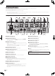
Operation Control Panel POWER b USB CD/ LINE PHONO DIGITAL USB MIC1 b CD/ LINE PHONO DIGITAL USB DECK 2 DECK 4 c c c c TRIM 10 7 0 2 LEVEL MIC 2 0 9 12 12 7 EQ 5 0 -26 / 6 6 EQ/ EQ/ - 7 -26 / LOW - 7 -26 / -24 -26 / 6 dB f COLOR 6 LINK f LOW 6 dB f CUE LOW 6 6 L dB LOW 6 HI CUE CUE L 6 6 8 FLANGER PHASER FILTER ROBOT CUE TRANS MONO SPLIT MELODIC SLIP ROLL SPIRAL 3 ROLL ECHO n 4 10 10 10 9 9 9 8 8 8 7 7 7 6 6 6 5 5 5 4 4
g COLOR control (page 16) This changes the parameters of the SOUND COLOR FX of the different channels. Basic Operation h Channel Fader (page 14) Adjusts the level of audio signals output in each channel. i CROSS FADER ASSIGN (A, THRU, B) selector switch (page 14) Sets the output destination of each channel to [A] or [B].
Switching the fader curve Audio is output from the [BOOTH] terminal Select the channel fader curve characteristics Switch the [CH FADER ( , , )] selector switch. — [ ]: The curve rises suddenly at the back side. — [ ]: A curve between the ones above and below is set. — [ ]: The curve rises gradually (the sound gradually increases as the channel fader is moved away from the front side). Switch the [CROSS FADER ( , , )] selector switch.
! Depending on the playing status of Serato DJ or the DJ player (off air, scratching, playing in reverse, etc.), it may not be possible to receive the GRID information. 2 Press the [ON/OFF] button of [BEAT EFFECTS] or touch the [X-PAD]. The effect is added to the sound in tempo with the track being played. ! When the [QUANTIZE] button is pressed again, the QUANTIZE function turns off. Using the FADER START function 1 Connect headphones to the [PHONES] terminal.
! — [AUTO]: The BPM is measured automatically from the audio signal that is being input. The [AUTO] mode is set when this unit’s power is turned on. — [TAP]: The BPM is input manually by tapping the [TAP] button with a finger. The [AUTO] BPM measurement range is BPM = 70 to 180. With some tracks it may not be possible to measure the BPM correctly. If the BPM cannot be measured, the BPM value on the display flashes. In such cases, use the [TAP] button to input the BPM manually.
[SND/RTN] [7/7 ] [1/7 ] [6/7 ] [2/7 [5/7 ] ] [3/7 [4/7 ] ] 3 Press the [BEAT c, d] button. Set the MIDI signal’s waveform output time. 4 Press the [ON/OFF] button of [BEAT EFFECTS] or touch the [X-PAD]. The MIDI message for turning the effect on is sent. ! When the [LFO FORM (WAKE UP)] button is pressed and a setting from [1/7 ] – [7/7 ] is selected, the MIDI message for the buttons and controls below can be sent even when the MIDI mode is turned off.
Types of effects Types of SOUND COLOR FX effects Effect Name Descriptions [COLOR] control SPACE DUB ECHO GATE/COMP NOISE CRUSH FILTER SPIRAL1 2 This function adds a reverberation effect to the input sound. When the delay time is changed, the pitch changes simultaneously. Input sound turned off Fade-out Time 1 beat BEAT c, d buttons (parameter 1) TIME control (parameter 2) LEVEL/DEPTH control (parameter 3) X-PAD (parameter 4) This function adds a reverberation effect to the input sound.
The cycle at which the cut-off frequency is moved fluctuates finely. X-PAD (parameter 4) BEAT c, d buttons (parameter 1) TIME control (parameter 2) LEVEL/DEPTH control (parameter 3) X-PAD (parameter 4) FLANGER1 Use these to set an effect time of 1/16 – 16/1 with respect to the time of one beat of the BPM. Use this to set the effect time. 10 to 4000 (ms) Use this to set the balance between the original sound and ROLL. Use this to set the effect time.
The MIDI signal waveform pattern switches each time the [LFO FORM (WAKE UP)] button is pressed. BEAT c, d buttons (parameter 1) TIME control (parameter 2) LEVEL/DEPTH control (parameter 3) X-PAD (parameter 4) ! Use these to set a waveform output time of 1/4 – 64/1 with respect to one beat of the BPM. Use this to set the waveform output time. — This changes the MIDI signal’s waveform pattern. When [MIDI LFO] is selected, the sound of the external effector connected to the [RETURN] terminal is not input.
MIDI assignment map MIDI assignment map ! ! “CC” is the abbreviation of “control change”. A control change is a type of MIDI signal used to transmit various types of control information, such as timbre, volume, etc. On this unit, values from 0 to 127 are output as CC mainly when controls and faders are operated. CC are also output when certain buttons are operated. “Note” is a MIDI term used when pressing or releasing notes on a piano or other keyboard.
Button/Control/Switch Name Category CC 045 — LEVEL/DEPTH X-PAD ON/OFF X-PAD (touch) ! When an effect other than [SND/RTN (MIDI LFO)] is selected at BEAT EFFECT ON/OFF X-PAD (touch) ! When [SND/RTN (MIDI LFO)] is selected at BEAT EFFECT HI LOW NOISE Control Control CC 091 CC 116 — — Button CC 114 2 OFF=0, ON=127 Button CC 064 2 OFF=0, ON=127 Control Control Button CC 030 CC 031 CC 085 — — Trigger/Toggle 0-127 0-127 OFF=0, ON=127 SPACE Button CC 105 Trigger/Toggle1 OFF=0, ON=127 GATE/
Changing the settings About the auto standby function 1 Press the [ON/OFF (UTILITY)] button for over 1 second. The [USER SETUP] mode setting screen is displayed. ! To display the [CLUB SETUP] mode setting screen, first turn this unit’s power off, then press the [POWER] button while pressing the [ON/OFF (UTILITY)] button. When [Auto Standby] is set to [ON], the standby mode is set automatically if 4 hours pass with all of the conditions shown below met.
Click the [MIXER INPUT] tab. Adjusting the buffer size (when using Windows ASIO) If an application using this unit as the default audio device (DJ software, etc.) is running, quit that application before adjusting the buffer size. Display the setting utility before starting. Click the [ASIO] tab. When Serato DJ is running and using this unit as the default audio device, set the audio data output in Serato DJ. Display the setting utility before starting. 1 Click the [MIXER OUTPUT] tab.
Additional information Troubleshooting ! ! Incorrect operation is often mistaken for trouble or malfunction. If you think that there is something wrong with this component, check the points below. Sometimes the trouble may lie in another component. Inspect the other components and electrical appliances being used. If the trouble cannot be rectified after checking the items below, ask your nearest Pioneer authorized service center or your dealer to carry out repair work.
Block Diagram MIC1 MIC1 LEVEL MIC2 SRC ADC PHONO Control Tone LAN ADC DIGITAL CH2 DAC CH1_Analog ADC PHONO Control Tone MASTER ADC BOOTH D SP TRIM REC SEND BOOTH MUTE REC MUTE SEND USB1/2 DIR Additional information DAC RETURN ADC DIGITAL MUTE DAC CH4_Analog ADC Control Tone MASTER 2 DAC CH3_Analog PHONO MUTE CH2_Analog DIR CH3 PHONES TRIM DIGITAL SRC CH_1_Digital/USB1/2 TRIM CD/LINE CH4 PHONES DAC Digital MASTER MIC CD/LINE DIT MASTER 1 DIR CD/LINE E
Acquiring the manual The operating instructions may be in a file in PDF format. Adobe® Reader® must be installed to read files in PDF format. If you do not have Adobe Reader, please install it from the download link on the CD-ROM’s menu screen. Downloading the latest versions of the operating instructions and the Quick Start Guide - Serato DJ Edition 1 Insert the CD-ROM into the computer’s CD drive. The CD-ROM menu is displayed.
Specifications General Power requirements................................................................................. AC 120 V, 60 Hz Power consumption....................................................................................................42 W Power consumption (standby)..................................................................................0.4 W Main unit weight......................................................................................... 7.1 kg (15.7 lb) Max.
En
PIONEER ELECTRONICS (USA) INC. LIMITED WARRANTY WARRANTY VALID ONLY IN THE U.S.A. AND CANADA WARRANTY Pioneer Electronics (USA) Inc. (PUSA) warrants that products distributed by PUSA in the U.S.A. and Canada that fail to function properly under normal use due to a manufacturing defect when installed and operated according to the owner ’s manual enclosed with the unit will be repaired or replaced with a unit of comparable value, at the option of PUSA, without charge to you for parts or actual repair work.
To register your product, find the nearest authorized service location, to purchase replacement parts, operating instructions, or accessories, please go to one of following URLs : Pour enregistrer votre produit, trouver le service après-vente agréé le plus proche et pour acheter des pièces de rechange, des modes d’emploi ou des accessoires, reportez-vous aux URL suivantes : In the USA & Canada/Aux Etats-Unis & Canada http://www.pioneerelectronics.com S018_B1_EnFr_PSV © 2013 PIONEER CORPORATION.