Owner’s Manual Mode d’emploi Manual de instrucciones MARINE MONO AMPLIFIER AMPLIFICATEUR MONOBLOC MARIN AMPLIFICATEUR MONOAURAL MARINO GM-ME300X1C English Français Español
Before you start Thank you for purchasing this PIONEER product To ensure proper use, please read through this manual before using this product. It is especially important that you read and observe WARNINGS and CAUTIONS in this manual. Please keep the manual in a safe and accessible place for future reference. Information to User Alteration or modifications carried out without appropriate authorization may invalidate the user’s right to operate the equipment.
The Safety of Your Ears is in Your Hands Get the most out of your equipment by playing it at a safe level—a level that lets the sound come through clearly without annoying blaring or distortion and, most importantly, without affecting your sensitive hearing. Sound can be deceiving. Over time, your hearing “comfort level” adapts to higher volumes of sound, so what sounds “normal” can actually be loud and harmful to your hearing.
While this amplifier is designed to be water-resistant, it should never be submerged under water or subjected to high-pressure water spray. Install the amplifier in a dry and well-ventilated environment, where other equipment will not interfere with it. When drilling holes in the chassis for installation, take precautions so as not to contact, damage or obstruct pipes, fuel lines, tanks or electrical wiring. Failure to take such precautions may result in fire.
level (counterclockwise). For use with an RCA equipped stereo (standard output of 500 mV), set to the NOR (normal) position. For use with an RCA equipped Pioneer headunit with maximum output of 4 V or more, adjust level to match that of the stereo output. For use with an RCA equipped headunit with output of 4 V, set to the H (High) position. If you hear too much noise when using the speaker input terminals, turn the gain control to higher level.
Gain volume of this unit 0.5 V (Maximum preout level=2 V) Precise Frequency Selection Chart The numbers in the illustration correspond to the Step Number. No.11 Maximum preout level=4V Above illustration shows NOR (normal) gain setting. 1DK@SHNMRGHOÐADSVDDMÐ@LOKHÆDQÐF@HMÐ and headunit output power If amplifier gain is raised improperly, this will simply increase distortion, with little increase in power.
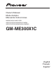
Connecting the units !DENQDÐBNMMDBSHMFÐSGDÐ@LOKHÆDQ Connection diagram WARNING Secure the wiring with cable clamps or adhesive tape. To protect the wiring, wrap sections in contact with metal parts in adhesive tape. Never cut the insulation of the power supply to feed power to other equipment. Current capacity of the wire is limited.
If you lose the supplied tool, use a flat screwdriver with a tip width of 3 mm or less as a substitute. Installation Before installing the @LOKHÆDQ Max 3 mm (1/8 in.) WARNING Connections when using the speaker input wire Connect the headunit speaker output wires to the amplifier using the supplied speaker input wire with RCA pin cord. Make sure to switch the INPUT SENS switch to SP.
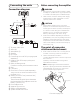
Ä (ÄMRS@KKÄSGDÄ@LOKH×DQÄVHSGÄSGDÄTRDÄNEÄ supplied tapping screws (4 mm × 25 mm). Additional information 2ODBHÆB@SHNMR 1 ② 3 4 1 Tapping-screws (4 mm × 25 mm) (5/32 in. × 1 in.) 2 Installation surface 3 Hole-to-hole distance: 224.4 mm (8-27/32 in.) 4 Hole-to-hole distance: 86.4 mm (3-13/32 in.) 4 Attach the top panel cover. Use the removed screws to attach the top panel cover (fastening torque 0.4 to 0.7 N·m).
"3 Ä2ODBH×B@SHNMR Power output....................... 300 W RMS × 1 Channel (at 14.4 V, 4 : 20 Hz to 240 Hz DQG 7+' 1 S/N ratio .............................. 75 dBA (reference: 1 W into 4 :) Accessories Power cable × 1 Speaker line input RCA cable × 1 Hexagonal wrench × 1 Mounting screw (4 × 25 mm) × 4 Supplied tool × 1 Notes Specifications and design are subject to modification without notice.
https://www.pioneerelectronics.com https://www.pioneerelectronics.ca PIONEER CORPORATION 28-8, Honkomagome 2-chome, Bunkyo-ku, Tokyo 113-0021, JAPAN PIONEER ELECTRONICS (USA) INC. P.O. Box 1540, Long Beach, California 90801-1540, U.S.A. TEL: (800) 421-1404 © 2020 PIONEER CORPORATION.
PIONEER ELECTRONICS (USA) INC. LIMITED WARRANTY WARRANTY VALID ONLY IN COUNTRY OF PRODUCT PURCHASE WARRANTY Pioneer Electronics (USA) Inc. (Pioneer) warrants that Pioneer® Car/Marine Electronics, Speaker, and Accessory Products distributed by Pioneer in the U.S.A.
PIONEER ELECTRONICS (USA) INC. GARANTIE LIMITÉE GARANTIE VALIDE UNIQUEMENT DANS LE PAYS D’ACHAT DU PRODUIT GARANTIE Pioneer Electronics (USA) Inc.