Gripper & Experimenter’s Module Manual version 1.
Gripper & Experimenter’s Module Copyright 1997, ActivMedia, Inc. All rights reserved. Under international copyright laws, this manual or any portion of it may not be copied or in any way duplicated without the expressed written consent of ActivMedia, Inc.
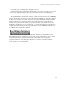
Pioneer Gripper & Experimenter’s Module Manual version 1.2, August 1997. Contents 1. INTRODUCTION 1 1.1 Gripper and Experimenter’s Package 1.1.1 Package Components 1.1.2 User Supplied Components 1 1 1 1.2 Basic Pioneer Platform 2 1.3 The Gripper & Experimenter’s Module 1.3.1 Gripper Description 1.3.2 Experimenter’s Module Description 2 2 4 1.4 Additional Resources 1.4.1 Pioneer Web Software Archive 1.4.2 Pioneer and Saphira Newsgroups 1.4.3 Support 5 5 5 6 2. INSTALLATION 2.1.
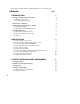
. EXPERIMENTER’S MODULE 15 4.1 I/O Ports 4.1.1 Digin: Self-Test 4.1.2 Digout: Self-Test 15 17 17 4.2 Programming the Digital I/O Ports 18 4.3 Programming the A/D Ports 18 4.4 Programming the Speaker 18 5. MAINTENANCE & REPAIR 19 5.1 Drive Lubrication 19 5.2 Gripper Belt Adjustments 19 5.3 Factory Repairs 19 6. APPENDIX A 20 Example C Program Demonstrates Gripper and Speaker Functions 7. APPENDIX B 24 Pioneer Server Information Packet 8.
Gripper & Experimenter’s Module 1. Introduction C ongratulations on your purchase and welcome to the rapidly growing community of researchers, developers, and enthusiasts of the Pioneer 1 Mobile Robot. This Pioneer 1 Gripper & Experimenter’s Module Manual provides the general and technical details you will need to install and operate your new Gripper and to develop your own attachments and enhancements for the Pioneer 1 Mobile Robot with the integrated Experimenter’s Module.
Overview 2.2 Basic Pioneer Platform Pioneer 1 is a small, mobile robot developed by Kurt Konolige of SRI International and Grinnell More of Real World Interface, Inc., and is available exclusively through ActivMedia, Inc.
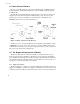
Gripper & Experimenter’s Module Figure 1-2 Pioneer Gripper side view. Figure 1-3. Pioneer Gripper top view In its fully down/open state, the two 2.5 inch (5cm) tall by 3.5 inch (9.5cm) deep Gripper paddles (each with 0.5cm foam pads on the inside) are 8.5 inches (21.5cm) apart and ride 1 inch (2.3cm) off the floor. The paddles extend out from the front robot’s main body 3 inches (10cm) beyond the console edge.
Overview In transition from the fully down/open position to their up/closed state, the Gripper paddles close together horizontally until they pinch an object or close on themselves. At that point, the entire Bar and Gripper Assembly rises up vertically—with or without an object in its grasp. Under software control, the Gripper then rises to a special “carry” position or all the way to the top of the Gripper case 4 inches (10.5 cm) off the floor to its closed/up position.
Gripper & Experimenter’s Module digital ports. There also is circuitry and a connector for an as-yet-implemented remotecontroller IR. A complete list of available I/O ports and connections can be found in Chapter 4, Experiment’s Module. 2.
Overview 2.4.3 Support Have a problem? Can’t find the answer in this or any of the accompanying manuals? Know a way that we might improve Pioneer 1? Share your thoughts and questions directly with us: pioneer-support@rwii.com Your message goes to our team of Pioneer developers who will help you directly or point you to where you may find help.
Gripper & Experimenter’s Module 3. Installation P lease read through this chapter carefully before you attempt to attach the Gripper & Experimenter’s Module to your Pioneer 1 Mobile Robot. If for any reason you do not wish to perform the work yourself, contact RWI and make arrangements to have the assembly installed at the factory. On the other hand, skip this chapter altogether if your Pioneer 1 Mobile Robot came with the Gripper & Experimenter’s Module Assembly already attached.
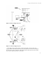
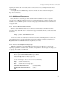
Installation Figure 2-1. Pioneer 1 microcontroller card 3.1.3 Step 3: Replace the PSOS EPROM Locate the EPROM/SRAM socket (Figure 2-2) on the microcontroller card and note that the Pin 1 locator notch on its case is towards the outer edge of the board—you’ll want to similarly position the new PSOS EPROM. Pry or pull out the socketed EPROM chip. We’d prefer that you use a special “chip-puller” tool, but if one isn’t handy, use a thin, flatFigure 2-2.
Gripper & Experimenter’s Module press carefully, but firmly down on the chip with your thumb or forefinger to seat it tightly in the socket. 3.1.4 Step 4 Reattach Microcontroller to Console By reversing the procedures you took in Step 2 and using the same tools and screws, reattach the Pioneer microcontroller to the Console top plate. Set the entire assembly aside for the moment in a safe place. 3.1.5 Step 5 Remove Nose The Gripper/Experimenter’s Module replaces the Pioneer’s nose.
Installation 3.1.8 Step 8 Re-Attach the Console Cables Carefully handling the Console top plate with attached microcontroller by its edges, reattach the various cables, front and back. Although the order is not critical, for convenience we recommend attaching the front cables firstthe sonar and drive (left and right) cables.
Gripper & Experimenter’s Module 4. Gripper Operation and Programming T he Pioneer Gripper comes fully integrated with the robot’s systems and software. The latest versions of PSOS (4.2+) contains support for direct control of the Pioneer’s onboard I/O that run the Gripper functions, as well as state-based software control routines that manage the Gripper functions for you. In turn, these PSOS functions are supported in Saphira (version 5.3+), the Pioneer Application Interface (PAI), and Pioneer-LOGO.
Gripper Operation and Programming 4.3 Gripper I/O The Gripper’s single drive motor is controlled through two digital output lines and under control of the microcontroller CPU: Output port OD0 controls the direction of rotation and OD1 enables/disables the motor. The act of gripping and raising objects is mechanical and dependent on the Gripper’s position—you cannot independently operate the gripper paddles. Rather, you drive the motor in one direction or the other.
Gripper & Experimenter’s Module The revised PSOS 4.2 (and later) sfCOMDIGOUT command has a two-byte argument: The high byte is a mask of those output bits you want to change, and the low byte is the bit pattern for the bits to change. This way, you don’t need to know the state of the port(s) you want to change; just the state in which you want them to be, and you won’t change the state of any of the other ports. The Saphira function, sfRobotCom2Bytes, packages the sfCOMDIGOUT command and values for you.
Gripper Operation and Programming Table 3-2.
Gripper & Experimenter’s Module 5.
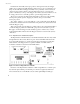
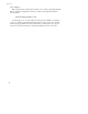
Experimenter’s Module Note also that the Nose (N) 16-pin and the General (G) 26-pin I/O connectors are numbered odd pins on top and even pins on the bottom; not top, left to right, then bottom left to right. The pinouts for the Nose connector, for example, are: 1 3 5 7 9 11 13 15 2 4 6 8 10 12 14 16 Table 4-1.
Gripper & Experimenter’s Module 5.1.1 Digin: Self-Test You may investigate the operation of the digital input and output ports through their PSOS self-test modes. After starting up your Pioneer, press the black Function button once to enable self-test mode. The LCD message should now display: BREAK, Boot to r eturn vv.vV* indicating that Pioneer has entered self-test mode. (Note that the voltage V reading will vary.
Experimenter’s Module 5.2 Programming the Digital I/O Ports Use the sfCOMDIGOUT PSOS command and the related Saphira convenience command to manage the various digital output ports. They are described in detail in the previous chapter. (PAI and P-LOGO support similar commands, too.
Gripper & Experimenter’s Module 6. Maintenance & Repair T he Pioneer Gripper is built to last a lifetime and requires little maintenance. 6.1 Drive Lubrication An occasional drop or two of oil on the guide rails is a very good idea. Place some thin, household oil on a Q-Tip or similar applicator, and rub along the rails. Then start up the Pioneer to exercise the Gripper and spread the lubricant. 6.
7. Appendix A Example C Program Demonstrates Gripper and Speaker Functions /* ################################################################ * gripper.c --- Saphira-based functions for controlling the gripper and speaker *################################################################# ** Copyright 1997 by Kurt Konolige ** ** The author hereby grants to SRI permission to use this software.
Gripper & Experimenter’s Module void sfRobotCom2Bytes(int com, int high, int low) { sfRobotComInt(com, ((high & 0xff)<<8) + (low & 0xff)); } /************************************************************* * Speaker functions -- play a tone string * * Format of string is L1 T1 L2 T2 ....
/* gripper control bits (DIGOUTPUT) */ #define sfGRIPSTATEMASK 0x05 /* picks out state bits in DIGOUTPUT */ #define sfGRIPMOTORBIT 0x02 /* motor bit, 0 is off, 1 is on */ #define sfGRIPDIRBIT 0x01 /* direction bit, 0 is down, 1 is up */ #define sfSPEAKERBIT 0x04 #define sfRIGHTLEDBIT 0x08 /* 0 is off, 1 is on */ #define sfLEFTLEDBIT 0x10 /* gripper sense bits (DIGINPUT) */ #define sfGRIPTOPBIT 0x01 /* top limit, 0 if hit */ #define sfGRIPMIDBIT 0x02 /* mid-level, 0 if hit */ #define sfGRIPBOTBIT 0x04 /* bot
Gripper & Experimenter’s Module case sfRIGHT: which = sfRIGHTLEDBIT; break; default: which = 0; } switch(state) { case sfOFF: sfRobotCom2Bytes(sfCOMDIGOUT, which, 0); break; case sfON: sfRobotCom2Bytes(sfCOMDIGOUT, which, which); break; } } 23
8.
Gripper & Experimenter’s Module 9. Index A A/D, 18 A/D port, 15 ActivMedia, Inc.
console removal, 7 EPROM location, 7 EPROM replacement, 7 microcontroller removal, 7 K R RC-servo controllers, 4 Real World Interface, ii Real World Interface, Inc., 2 RobotCom2Bytes, 13 RWI, ii. See Real World Interface, Inc.
Gripper & Experimenter’s Module 27
Warranty & Liabilities Your Pioneer 1 Mobile Robot and its accessories are fully warranted against defective parts or assembly for 90 days after it is shipped to you from the factory. This warranty explicitly does not include damage from shipping or from abuse or inappropriate operation, such as if the robot is allowed to tumble or fall off a ledge, or if it is overloaded with heavy objects.