DJ MIXER DJM-800 Operating Instructions
Thank you for buying this Pioneer product. Please read through these operating instructions so you will know how to operate your model properly. After you have finished reading the instructions, put them away in a safe place for future reference. In some countries or regions, the shape of the power plug and power outlet may sometimes differ from that shown in the explanatory K015 En drawings. However the method of connecting and operating the unit is the same.
We Want You Listening For A Lifetime Selecting fine audio equipment such as the unit you’ve just purchased is only the start of your musical enjoyment. Now it’s time to consider how you can maximize the fun and excitement your equipment offers. This manufacturer and the Electronic Industries Association’s Consumer Electronics Group want you to get the most out of your equipment by playing it at a safe level.
CONTENTS FEATURES CAUTIONS REGARDING HANDLING ........................ 3 CONFIRM ACCESSORIES ........................................... 4 FEATURES ................................................................... 4 BEFORE USING CONNECTIONS ............................................................ 5 CONNECTION PANEL ........................................... 5 CONNECTING INPUTS .......................................... 6 CONNECTING EXTERNAL EFFECTORS, OUTPUT CONNECTORS ............................
CONNECTIONS (CONNECTION PANEL) CONNECTIONS CONNECTION PANEL 1 2 3 4 5 6 7 SIGNAL GND SIGNAL GND MASTER 2 L PHONO REC PHONO LINE 8 L LINE PHONO L DIGITAL IN LINE CD L CD L POWER OFF ON CONTROL 1GND 2HOT R R DIGITAL LINE 3COLD AC IN CONTROL R CONTROL R DIGITAL LINE DIGITAL CD CONTROL R MIDI OUT DIGITAL OUT fs (Hz) DIGITAL CD 48 k 96 k MASTER ATT 0dB -3dB -6dB -12dB R 21 ADD CUT MASTER 1 L 20 R MIC SIGNAL 19 BOOTH (TRS) 18 17 1. POWER switch 2.
CONNECTIONS (CONNECTING INPUTS) Always turn off the power switch and disconnect the power plug from its outlet when making or changing connections. CONNECTING INPUTS Pioneer DJ CD players Connecting other line level output devices Connect a DJ CD player’s audio output connectors to one of the channel 1 to 2 CD input connectors or the channel 3 to 4 LINE input connectors, and connect the player’s control cable to the corresponding channel’s CONTROL connector.
CONNECTIONS (CONNECTING EXTERNAL EFFECTORS, OUTPUT CONNECTORS/ABOUT MIDI CONNECTORS) CONNECTING EXTERNAL EFFECTORS, OUTPUT CONNECTORS Master output Digital output This unit is furnished with balanced output MASTER 1 (supporting XLR plugs), and unbalanced output MASTER 2 (supporting RCA plugs). Using the MASTER ATT switch, adjust the output level to match the input sensitivity of the power amplifier used.
CONNECTIONS (CONNECTING MICROPHONE AND HEADPHONES/CONNECTING THE POWER CORD) CONNECTING MICROPHONE AND HEADPHONES Microphone Headphones The MIC 1 jack on the upper surface of the operating panel can be used to connect a microphone with Ø6.3 mm phone plug or XLR plug. The MIC 2 jack on the upper surface of the operating panel can be used to connect a microphone with Ø6.3 mm phone plugs.
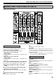
NAMES AND FUNCTIONS OF PARTS (OPERATION PANEL) NAMES AND FUNCTIONS OF PARTS OPERATION PANEL POWER MASTER MIC MIC 1 CD /DIGITAL MIC 2 9 11 TRIM OVER 1 2 3 CD /DIGITAL LINE 2 -26 MID –3 6 EQ –7 +6 -12 7 8 -26 +6 –7 14 –15 –15 dB -26 15 COLOR 42 43 +6 13 15 –7 LOW 14 –10 –15 dB +6 COLOR 42 43 –2 EQ –3 –5 -26 +6 13 –7 14 –15 –10 15 dB +6 43 COLOR 42 BEAT –15 –24 –24 -26 24 32 –5 LOW –10 –24 dB -26 +6 –1 –3 -26 –7 14 0 MID –2 EQ –5
NAMES AND FUNCTIONS OF PARTS (OPERATION PANEL) 11. TRIM adjust dial 21. Cross fader curve switch (CROSS FADER) Use to adjust the input level for each channel. (adjustable range: –∞ to +9 dB, mid-position is about 0 dB) This switch allows the user to select from three types of cross fader curve response. ¶ At the left setting, the curve produces a rapid signal rise. (As soon as the cross fader lever leaves the [A] side, the [B] channel sound is produced.
NAMES AND FUNCTIONS OF PARTS (OPERATION PANEL) 30. Headphones level adjust dial (LEVEL) Adjusts the output level of the headphones jack. (adjustable range: –∞ to 0 dB) 31. Headphones jack (PHONES) BPM counter section 32. Beat select buttons (2 BEAT 3) 3 (Beat up): Doubles the calculated BPM. 2 (Beat down): Halves the calculated BPM. (P. 17) ¶ Some effects can be set for “3/4”. 33. MIDI start/stop button (MIDI START/STOP) Use to alternate the MIDI control function between start and stop (P. 20).
NAMES AND FUNCTIONS OF PARTS (DISPLAY SECTION) 2. Channel select display section DISPLAY SECTION EFFECT SELECT 1 The indicator lights constantly, and a red frame lights around the number position corresponding to the chosen effect channel selector. 3. Parameter display section Upper MIDI : The indicator lights constantly. AUTO/TAP: [AUTO] lights when the BPM measuring mode is set to AUTO, and [TAP] lights when the BPM measuring mode is set to manual (TAP).
MIXER OPERATIONS (BASIC OPERATIONS) MIXER OPERATIONS [Selecting Stereo or Monaural] BASIC OPERATIONS When the STEREO/MONO switch is set to [MONO], the master output becomes a monaural combination of L+R channels. 1 POWER [Microphone Input] 1. To use a microphone, set the MIC switch to [ON] or [TALK OVER].
MIXER OPERATIONS (FADER START FUNCTION) 7 Use the CROSS FADER curve switch to select the cross fader curve response. 4. At the instant you wish to start playback, move the channel fader lever. ¶ At the left setting, the curve produces a rapid signal rise. (As soon as the cross fader lever leaves the [A] side, the [B] channel sound is produced.) ¶ At the right setting, the curve operates to produce an even, neutral rise throughout the cross fader’s movement.
EFFECT FUNCTIONS (TYPES OF BEAT EFFECTS) EFFECT FUNCTIONS This unit can produce beat effects linked to the BPM, and sound-color effects linked to the COLOR dials provided for each channel, for a total of 18 basic effects (including [SND/RTN]). In addition, by changing the parameters for each kind of effect, an extremely wide range of effect variations can be produced.
EFFECT FUNCTIONS (TYPES OF BEAT EFFECTS) 6. FILTER 12. ROLL In units of 1/4, 1/2, 1/1, 2/1, 4/1, 8/1, 16/1, 32/1, or 64/1 beat, the filter frequency is moved, greatly changing the sound coloration. Sounds of 1/16, 1/8, 1/4, 1/2, 1/1, 2/1, 4/1, 8/1, or 16/1 beat are recorded and output repetitively. Also, when sounds are changed from 1/1 beat to 1/2 or 1/4 in synch with the beat, a roll sound effect can be produced.
EFFECT FUNCTIONS (PRODUCING BEAT EFFECTS) PRODUCING BEAT EFFECTS Display example EFFECT SELECT Effect Name: DELAY 4 BEAT 2, 3 1 AUTO/TAP TAP CH SELECT 1 MIC 2 3 TIME 2 A 3 B 4 MST PARAMETER AUTO TAP MIDI BPM % LEVEL/DEPTH 1. Press the AUTO/TAP button to set the Beats Per Minute (BPM = track speed) measuring mode. AUTO:The BPM of the input music signal is detected automatically. TAP: The BPM is input manually by tapping on the TAP button.
EFFECT FUNCTIONS (TYPE OF SOUND-COLOR EFFECT/USING SOUND-COLOR EFFECTS) TYPE OF SOUND-COLOR EFFECT USING SOUND-COLOR EFFECTS 1. HARMONIC Detects deviation of the input sound from absolute pitch and automatically compensates to the nearest key. By rotating the dial, the pitch/key can be adjusted within a range of ±6 half-tones. 1 HARMONIC, SWEEP, FILTER, CRUSH COLOR Input sound Compensated sound LOW HI 2 COLOR 2.
EFFECT FUNCTIONS (EFFECT PARAMETERS) EFFECT PARAMETERS Beat Effect (*1) Name Beat Switch Parameter Parameter 1 (TIME dial) Contents Setting Range (unit) Parameter 2 (MIX/DEPTH dial) contents 1 DELAY Sets delay time of 1/8 to 16/1 per 1 beat of BPM time. Sets delay time. 1 to 4 000 (ms) Sets balance between original and delay sound. 2 ECHO (*2) Sets delay time of 1/8 to 16/1 per 1 beat of BPM time. Sets delay time. 1 to 4 000 (ms) Sets balance between original sound and echo sound.
MIDI SETTINGS MIDI SETTINGS MIDI is an acronym for “Musical Instrument Digital Interface” and refers to a protocol developed for the exchange of data between electronic instruments and computers. A MIDI cable is used to connect components equipped with MIDI connectors to enable the transmission and receipt of data. The DJM-800 uses the MIDI protocol for transmitting and receiving data about component operation and BPM (timing clock).
MIDI SETTINGS Category Switch Name CH4 CROSS FADER FADER CURVE MASTER BOOTH EFFECT MIC (SOUND COLOR FX) (FADER START) (HEAD PHONES) MIDI MIDI Message Switch Type MSB TRIM HI MID LOW COLOR CUE FADER CF ASSIGN CROSS FADER CH CURVE CROSS CURVE MASTER LEVEL BALANCE CUE MONITOR BEAT LEFT BEAT RIGHT AUTO/TAP TAP CUE EFFECT SELECT CH SELECT TIME VR VR VR VR VR BUTTON VR SW VR SW SW VR VR BUTTON VR BUTTON BUTTON BUTTON BUTTON BUTTON SW SW SW Bn Bn Bn Bn Bn Bn Bn Bn Bn Bn Bn Bn Bn Bn Bn Bn Bn Bn Bn Bn
TROUBLESHOOTING TROUBLESHOOTING Incorrect operations are often mistaken for trouble and malfunctions. If you think there is something wrong with this component, check the points below. Sometimes the trouble may originate from another component. Thus, also check the other electrical appliances also in use. If the trouble cannot be rectified even after checking the following items, contact your dealer or nearest PIONEER service center.
SPECIFICATIONS SPECIFICATIONS 1. General 3. Input/output connector systems Power source .............................................................. AC 120 V, 60 Hz Power consumption ..................................................................... 32 W Operating temperature ..................... +5 ˚C to +35 ˚C (+41 ˚F to +95 ˚F) Operating humidity .................... 5 % to 85 % (without condensation) Weight .......................................................................... 8.0 kg (17.
BLOCK DIAGRAM BLOCK DIAGRAM MIC MIC 1 LEVEL MIC AMP MIC 1 MUTE MIC 1 MIC 2 A/D MIC 2 LEVEL MIC AMP PHONES D/A MASTER D/A PHONES MIC 2 MASTER ATT. CH 1 BUFFER TRIM LINE BUFFER MUTE MASTER 1 BUFFER A/D MUTE CD MASTER 2 CH 1 DIGITAL SRC DIR DIGITAL/CD SW. CD/DIGITAL LINE SW. CD/DIGITAL LINE LINE CD CD LINE DIGITAL DIGITAL CH 2 SRC DIT -COM DSP AMP. MUTE BUFFER AMP. MUTE D/A BOOTH VR AD PHONO/LINE SW. DIGITAL SEL. DIGITAL /ANALOG SW.