UNIVERSAL REAR-VIEW CAMERA CAMERA DE RECUL UNIVERSELLE Owner’s Manual Mode d’emploi ND-BC5
This device complies with part 15 of the FCC Rules. Operation is subject to the following two conditions: (1) This device may not cause harmful interference, and (2) this device must accept any interference received, including interference that may cause undesired operation. Information to User Alteration or modifications carried out without appropriate authorization may invalidate the user’s right to operate the equipment.
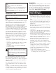
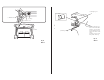
Installation Parts supplied 𝖠 𝖡 𝖢 𝖣 𝖤 𝖥 𝖦 𝖧 𝖨 Rear view camera × 1 RCA power supply cable × 1 Power supply unit × 1 Hexagon wrench × 1 Hook and loop fastener (soft type) × 1 Hook and loop fastener (hard type) × 1 Clamp × 6 Waterproof pad × 1 Double-sided tape × 1 Installation example (Fig.
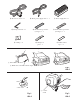
𝖠 Rear view camera × 1 𝖡 RCA power supply cable × 1 𝖣 Hexagon wrench × 1 𝖤 Hook and loop fastener (soft type) × 1 𝖦 Clamp × 6 𝖧 Waterproof pad × 1 𝖢 Power supply unit × 1 𝖥 Hook and loop fastener (hard type) × 1 𝖨 Double-sided tape × 1 ③ Install on the center part ① Glass surface ② Make sure it doesn’t touch the wiper Fig. 2 Abb. 2 Fig. 1 Abb. 1 ① Camera stand Fig. 3 Abb.
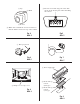
② Top ③ Mark ⑥ Be sure not to hide any part of the characters on the license plate when attaching the camera. ④ Bottom ⑤ Make sure to install the rear view camera so that the mark is located on top of the camera. Fig.5 Abb. 5 Fig. 4 Abb. 4 ① Hexagon wrench Fig. 6 Abb. 6 Fig. 7 Abb. 7 ① Power supply unit ② Bumper or rear edge of car Fig. 8 Abb. 8 ② Hook and loop fastener (hard type) ③ Hook and loop fastener (soft type) Fig. 9 Abb.
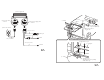
① Power supply unit ② Rear view camera connector ③ RCA power supply cable connector ① Clamps ② Rear view ⑤ Power supply camera unit ④ Product with a video input jack (Hideaway unit etc.) ③ RCA power supply cable ④ Rear view camera 3 m (9 ft. 10 in.) ⑤ RCA pin ⑦ Fuse (1A) 3 m (9 ft. 10 in.) ⑥ Red 7 m (23 ft. 4 in.) ⑥ Made with a rasp etc. 1.5 m (4 ft. 11 in.) ⑦ Scuff plate ⑧ Black Fig. 10 Abb. 10 ⑧ Clamp ⑨ Waterproof pad Attach the waterproof pad using double-sided tape. Fig. 11 Abb.
② Waterproof pad ① Clamps ① Pull out from here ② Hinge ③ Harness cover ④ Rear view camera ⑤ Hatch ③ Rubber packing Fig. 12 Abb. 12 ④ Make a U-shaped loop in the lead outside the rubber packing to prevent rainwater from flowing along the lead into the interior of the vehicle. Attach the waterproof pad using double-sided tape. Fig. 13 Abb.
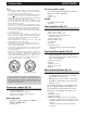
Connection Accessory power supply Note: OF O F O N F ACC N OF • This unit is for vehicles with a 12-volt battery and negative grounding. Before installing it in a recreational vehicle, truck, or bus, check the battery voltage. • To avoid shorts in the electrical system, be sure to disconnect the battery cable before beginning installation. • Refer to the owner’s manual for details on connecting the other units, then make connections correctly.
Specifications Power source ........................................... 14.4 V DC (10.8 V to 15.1 V allowable) Grounding system .............................. Negative type Max. current consumption .......................... 100 mA Output video ....................................... Mirror image (for rear view confirmation) Sensor ......................... 1/4-inch color CMOS sensor No. of pixels .................. effective no. of pixels roughly 310 000 Lens ...............................................
PIONEER CORPORATION 1 1, Shin ogura, Saiwai ku, Kawasaki shi, Kanagawa 212 0031, JAPAN PIONEER ELECTRONICS (USA) INC. P.O. Box 1540, Long Beach, California 90801 1540, U.S.A. TEL: (800) 421 1404 PIONEER EUROPE NV Haven 1087, Keetberglaan 1, B 9120 Melsele, Belgium/Belgique TEL: (0) 3/570.05.11 PIONEER ELECTRONICS ASIACENTRE PTE. LTD. 253 Alexandra Road, #04 01, Singapore 159936 TEL: 65 6472 7555 PIONEER ELECTRONICS AUSTRALIA PTY. LTD.