ビデオカード VIDEO CARD CARTE VIDEO VIDEOKARTE PDA-5002 取扱説明書 Operating Instructions Mode d’emploi Bedienungsanleitung
Contents Safety Precautions .................................. i English Before Proceeding .................................. 2 How to Use This Manual .............................................. 2 Checking Supplied Accessories ................................... 3 Part Names and Functions .................... 4 Connection Panel .......................................................... 4 Installation and Connections ................ 6 Installing the Video Card .........................................
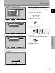
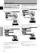
Before Proceeding Press MENU to display the menu screen. MAIN MENU INPUT1 PICTURE SCREEN : CO NT RA S T 0 : BR I GHT . 0 : +60 R. L E V E L : +60 G. L E V E L : +60 B. L E V E L : 0 H . E NH AN CE : V . E NH AN CE 0 SET UP Checking Supplied Accessories OPTION English 1 Check that the following accessories were supplied. 1 Label for remote control unit RE S E T SELECT ENTER MENU EXIT 2 BNC/Pin conversion adaptor Press 3 to select SCREEN.
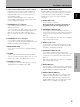
Part Names and Functions Connection Panel English AC INLET INPUT5 AUDIO DIGITAL RGB R ! R 8Ω ~16Ω SPEAKER + — 1 CONTROL IN OUT 2 L INPUT4 VIDEO AUDIO R 4 Plasma Display Section The plasma display is provided with 2 video input connectors, 1 video output connector, audio input/output jacks and speaker terminals. There are also CONTROL IN/OUT jacks for connection of PIONEER components with the Î mark.
Part Names and Functions 9 AUDIO INPUT (Stereo mini jack) Use to obtain sound when INPUT1, INPUT2 or INPUT5 is selected. Connect this jack to the audio output connector of the device connected to the plasma display’s INPUT1 or INPUT2, or to the audio output connector of the device connected to the video card’s INPUT5 (page 12). 0 AUDIO OUTPUT (Stereo mini jack) Use to output the audio of the selected source component connected to the plasma display to an AV amplifier or similar component (page 12).
Installation and Connections English Installing the Video Card 2 Insert the video card gently and evenly in alignment with the two rails (black) visible inside the installation port. TO USERS: Note This component is sold with the understanding that it will be installed by a specialist possessing appropriate technical knowledge and ability. Be very careful when inserting the card. Insert straight! The card or display may be damaged if the card is inserted crooked or with excessive force.
Installation and Connections Connection to INPUT1 and INPUT2 Consult the following chart when making connections to a plasma display equipped with this video card (pages 7 to 12). Input Connector INPUT INPUT INPUT INPUT INPUT Connected 1*1 2*1 3 4 5 component and signals AV component Various components can be connected to the INPUT1 and INPUT2 jacks. After connections are made, on-screen setup is necessary to match the characteristics of the connected component.
Installation and Connections English Connection to AV components Connection to AV component that has component video jacks Make component video connections for AV components such as DVD and LD players or similar components with component video output capability. Connection of G ON SYNC analog RGB source Make G ON SYNC connections for a component with output that has the synchronization signal layered on top of the green signal.
Installation and Connections Make composite SYNC connections for a component with output that has the vertical synchronization signal layered on top of the horizontal synchronization signal. Connection to a personal computer English Connection of composite SYNC analog RGB source Connection method differs depending on the computer type. When connecting, please thoroughly read the computer’s instruction manual.
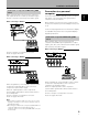
Installation and Connections When connecting to INPUT1 Connection to INPUT3 INPUT1 English ANALOG RGB OUTPUT (ANALOG RGB) Connect an AV component that has S-video output jack to the video card’s S-VIDEO input jack. AUDIO INPUT3 S-VIDEO R L Connect the cable corresponding to the shape of the input terminal on the display and the personal computer’s output terminal. Secure by tightening the terminal screws on both units. AV component After connecting, on-screen setup is necessary.
Installation and Connections A computer equipped with DVI output (digital RGB signal) can be connected to the video card’s DVI connector. INPUT5 DIGITAL RGB NOTICE ¶ INPUT 5 supports Microsoft “Plug & Play” (VESA DDC 2B) components. See Supplement 3 (page 33) when making connections to INPUT 5. ¶ See Supplement 2 (page 32) for information regarding signals and display formats supported by INPUT 5.
Installation and Connections Audio connection for component connected to INPUT3 English Audio Connections Before making connections, be sure to check that the audio component’s power and the display’s main power is off. AUDIO R INPUT3 S-VIDEO L Connect an audio component to the audio input jack of the plasma display with installed video card. When the video card is installed, the plasma display provides three audio input jacks and one audio output jack.
Installation and Connections English How to Route Cables Speed clamps and bead bands are included with the plasma display for bunching cables together. Once components are connected, follow the following steps to route cables. * As viewed from the rear of the display. 1 2 time and may be damaged when removed. Organize cables together using the provided speed clamps. Insert 1 into an appropriate hole on the rear of the unit, then snap 2 into the back of 1 to fix the clamp.
Setting Up the System 7 English Setup after Connection Press 2/3 to select the display mode. After components have been connected to INPUT1, INPUT2 or INPUT5, on-screen setup is necessary. Follow the procedure described below and make settings as they apply to the type of components connected. Setting the Screen Mode / Input Signal Format 1 2 3 4 S E T T I N G : V GA Switch MAIN POWER on the connection panel to the on position to turn on the display’s main power. The STANDBY/ON indicator lights red.
Setting Up the System 2 Press 2/3 to select SET UP. MAIN MENU PICTURE Set SETTING and VIDEO SIGNAL as follows. SET UP Component video output of a DVD player, etc. VIDEO COMPONENT RGB video output of a video deck etc.
Operations 3 English Selecting an Input Source This section explains the basic operation of the plasma display. Outlined on the following pages is how to turn the main power on and off, put this display in the operation or standby mode and how to select connected components. Press INPUT on the remote control unit or the display to select the input. Input changes each time the display’s INPUT is pressed as follows.
Operations To confirm display settings English To adjust the volume DISPLAY VOLUME +/– Press VOLUME on the remote control unit. Use VOLUME + or VOLUME – to adjust the volume of the connected speakers. Press DISPLAY on the remote control unit. The currently selected input, screen size and refresh rates will be displayed for about 3 seconds. : I NPUT 1 5 To mute the sound fH: fV: Operations V O L U ME 3 1. 5 kH z 60.
Operations English Notes Screen Size Selection ÷ When the WIDE, ZOOM, or FULL setting is used to display a non-wide screen 4:3 picture fully on a wide screen, a portion of the picture may be cut off or appear deformed. The plasma display incorporates screen modes of various height and width ratios. For optimal viewing, we recommend that you select the screen mode that best matches the video source that you are viewing.
Operations Partial Image Enlargement (POINT ZOOM) This display allows any one of nine screen areas (AREA 1 to AREA 9) to be selected and enlarged to 1.5x, 2x, 3x, or 4x. When performing point zoom enlargement, the direction buttons (5/∞/2/3) can be used to move the enlarged portion up-down and right-left. 1 4 P.ZOOM SET 3 x 1.5 3 x 2.0 x 4.0 2 x 3.0 2 ÷ When the zoom ratio is changed, the screen image is enlarged based on the screen center.
Operations 3 English Automatic Power OFF The plasma display is equipped with automatic powermanagement and auto-power-off functions, which allow the unit to automatically switch to power-saving mode when no sync signal is detected. (A warning message appears on-screen before these functions operate.) Press 5/∞ to select either the POWER MANAGEMENT or AUTO POWER OFF mode.
Display Panel Adjustments Press MENU to display the menu screen. MAIN MENU PICTURE CO NT RA S T BR I GHT. C O L OR T I NT S H A RP INPUT4 SET UP : 0 : 0 : 0 : 0 : 0 5 When the setup is finished, press MENU to exit the menu screen. OPTION Note Make these adjustments for each input (INPUT1 to INPUT5) and signals. PICTURE mode adjustment items Below are brief descriptions of the options that can be set in the PICTURE mode.
English Display Panel Adjustments Adjusting the Image Position and Clock (Automatic Adjustment) Manual Adjustment of Screen Position and Clock Pressing AUTO SET UP on either the display or the remote control unit will adjust the screen position and clock to optimum values. This setting can be adjusted when a computer signal is connected to INPUT1, INPUT2, or INPUT5. (The settings on this page are not supported when INPUT3 or INPUT4 is selected, or when a video signal is input).
3 Press 5/∞ to select the adjustment item, then press SET. MAIN MENU PICTURE INPUT1 SCREEN : POS I T I ON CL OC K / P HA S E : SET UP 0 / 0 / OPTION 0 0 RE S E T SELECT 4 SET ENTER MENU EXIT Press 2/3 to carry out the adjustment. SCREEN mode adjustment items Below are brief descriptions of the options that can be set in the SCREEN mode. POSITION H.POSITION ·········· Adjust the picture’s position to the left or right. V.POSITION ·········· Adjust the picture’s position upward or downward.
English Other Operations 5 Rewriting the Input Display (INPUT LABEL) Press 2/3/5/∞ to select the first desired character (here, “C”), then press SET to confirm (repeat this step to input up to eight desired characters.) I NPUT 1 This function allows rewriting of the screen contents displayed with differing inputs. For example, the default “INPUT1” can be changed to “COMPUTER” or other name describing the connected component (up to maximum of 8 characters). I N P UT Press INPUT and set input to INPUT1.
Other Operations Reducing Video Noise (DIGITAL NR) Make this setting if video noise is objectionable. 1 1 Press MENU to display the menu screen. Press MENU to display the menu screen. MAIN MENU PICTURE CO NT RA S T BR I GHT . C O L OR T I NT S H A RP MAIN MENU INPUT1 SET UP : 0 : 0 : 0 : 0 : 0 English Changing the Color Temperature (COLOR TEMP) INPUT1 PICTURE SET UP : CO NT RA S T 0 : BR I GHT .
Other Operations English Setting the PureCinema mode When the PureCinema mode is selected, it functions automatically to detect video signals of movies recorded at 24 frames-per-second, changing the scan settings to allow enjoyment of higher quality movie playback. It does this by converting the video signal to progressive scan. When using the PureCinema function, it should odinarily be set to “HQ.
Other Operations 3 AUTO 3 NTSC 3 PAL 2 Press 2/3 to select SET UP. MAIN MENU PICTURE PICTURE 3 SECAM INPUT4 SET UP : I N P UT 4 : OF F : M I DD L E : L OW : OF F : OF F : N TSC : MO T I ON SELECT 3 5 CHANGE MENU SELECT 4 When viewing a fast moving picture such as might be experienced with a sports program, setting this mode to “MOTION” will reduce picture blur and create a clearer image.
English Other Operations When viewing an image from INPUT1 or INPUT2, the following screen is displayed. Viewing in a Bright Location (HIGH CONTRAST) MAIN MENU PICTURE When viewing a picture in a bright location, setting this mode to “ON” will enable you to obtain a clear video image. Press MENU to display the menu screen. The menu screen appears. MAIN MENU PICTURE CO NT RA S T BR I GHT.
Other Operations AUTO FUNCTION The plasma display is equipped with an AUTO FUNCTION detection function; when a signal is detected at the selected input, the function selector automatically switches to that input. 3 OFF INPUT4 2 ÷ When OFF is selected, AUTO FUNCTION is disabled. ÷ After INPUT 1 or INPUT 4 is selected, if a signal is detected to the selected input jack, the input function will automatically switch to the selected input.
Other Operations 3 Audio Output (AUDIO OUT) Press 5/∞ to select AUDIO OUT. MAIN MENU English PICTURE SET UP OPTION POWE R C O N T R O L : S T A ND A RD A U T O F U N C T I O N : OF F : F I X ED A UD I O O U T The signal level produced at the AUDIO OUT jack can be set to FIXED or VARIABLE (linked to the VOLUME) as desired. 1 INPUT1 SCREEN Press MENU; The onscreen menu will be displayed. MAIN MENU INPUT1 PICTURE SCREEN : CO NT RA S T 0 : BR I GHT . 0 : + R. L E V E L 60 : +60 G.
Additional Information English Specifications General External dimensions .... 243.8 (W) x 23.6 (H) x 144 (D) mm 9–5/8 (W) x 29/32 (H) x 5–11/16 (D) in. Weight ................................................... 1.2 kg (2 lbs. 1 oz) Operating temperature range ..... 0 to 40 °C (32 to 104 °F) Input/output Video INPUT 3 Input INPUT 4 Input S terminal (Mini DIN 4 pin) • Y/C saparate video signal Y . . . 1 Vp-p/75 Ω/negative sync. C . . . 0.286 Vp-p/75 Ω (NTSC) 0.
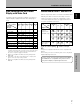
Additional Information Supplement 1 English Video signal compatibilty table (INPUT1, INPUT2) Refresh rate Vertical FV (Hz) Screen size Horizontal FH (kHz) 15.625 50 28.1 31.25 15.734 31.5 60 33.75 45.0 67.
Additional Information INPUT 5 (DVI female connector) pin allocation. Pin No. 1 2 3 4 5 6 7 8 9 10 11 12 13 14 15 16 17 18 19 20 21 22 23 24 8 17 24 16 Aspect ratio The TV screen’s width to height ratio is referred to as its aspect ratio. The aspect ratio on standard TVs is 4:3 and on wide TVs or High Definition TVs it is 16:9. S jack (S VIDEO jack) Signal Assignment T.M.D.S. Data2– T.M.D.S. Data2+ T.M.D.S. Data2/4 Shield NC (No connection) NC (No connection) DDC Clock DDC Data NC (No connection) T.