
Computer Hardware User Manual


8
En
English
Installation and Connections
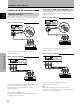
Connection of G ON SYNC analog RGB source
Make G ON SYNC connections for a component with
output that has the synchronization signal layered on top
of the green signal.
When connecting to INPUT1
On screen setup is necessary after connection.
Please see pages 14 and 15.
When connecting to INPUT2
On screen setup is necessary after connection.
Please see pages 14 and 15.
Note
When making G ON SYNC connections, do not make any
connections to the VD or HD jacks. If connections are made, the
picture may be not displayed normally.
Installation and Connections
GBRHD VD
(ON SYNC) (H/V SYNC)
Ô
75 2.2
Ω kΩ
INPUT2
ANALOG RGB (ANALOG RGB)
INPUT1
OUTPUT
Connection to AV components
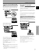
Connection to AV component that has
component video jacks
Make component video connections for AV components
such as DVD and LD players or similar components with
component video output capability.
When connecting to INPUT1
On-screen setup is necessary after connection.
Please see page 14.
When connecting to INPUT2
Connect the Y signal to the G jack, the C
B/PB signal to the
B jack, and the C
R/PR signal to the R jack.
On-screen setup is necessary after connection.
Please see page 14.
INPUT2 jacks are all BNC jacks.
If necessary, use BNC/pin conversion adapters (1 (one)
included) to make connections.
GBRHD VD
(ON SYNC) (H/V SYNC)
Ô
75 2.2
Ω kΩ
INPUT2
ANALOG RGB (ANALOG RGB)
INPUT1
OUTPUT