Plasma Display PDP-424MV Contents related to system specifications, power requirements, accessories, and other information differ with respect to the country where this unit is purchased. For customers living in the U.S.A. or Canada, please use and refer to the instructions written in either English or French. For customers in Japan, please use and refer to the instructions written in Japanese.
English Operating Instructions Thank you very much for purchasing this PIONEER product. Before using your Plasma Display, please carefully read the “Important Information” and these “Operating Instructions” so you will know how to operate the Plasma Display properly. Keep this manual in a safe place. You will find it useful in the future. Notes on Installation Work: This product is marketed assuming that it is installed by qualified personnel with enough skill and competence.
English Important Information Precautions Warnings and Safety Precaution Please read this manual carefully before using your plasma monitor and keep the manual handy for future reference. This plasma monitor is designed and manufactured to provide long, trouble-free service. No maintenance other than cleaning is required. Please see the section “Plasma monitor cleaning procedure” on the next page. The plasma display panel consists of fine picture elements (cells) with more than 99.
DVI cable (not supplied) band core (small) Power cable (supplied) band Connector core (small) core (large) core (large) To avoid damage and prolong operating life: 1. Use only with 100-240V 50/60Hz AC power supply. Continued operation at line voltages greater than 100240 Volts AC will shorten the life of the unit, and might even cause a fire hazard. 2. Handle the unit carefully when installing it and do not drop. 3. Set the unit away from heat, excessive dust, and direct sunlight. 4.
English IMPORTANT NOTICE The serial number for this equipment is located on the rear panel. Please write this serial number on your enclosed waranty card and keep in a secure place. This is for your security. This Class B digital apparatus complies with Canadian ICES-003. Caution This model is for use with the following optional accessories. Use with other optional accessories is capable of resulting in instability causing possible injury.
Read these instructions. Keep these instructions. Heed all warnings. Follow all instructions. Do not use this apparatus near water. Clean only with a dry cloth. Do not block any of the ventilation openings. Install in accordance with the manufacturers instructions. 8. Do not install near any heat sources such as radiators, heat registers, stoves, or other apparatus (including amplifiers) that produce heat. 9. Do not defeat the safety purpose of the polarized or grounding-type plug.
English Important Information Should this product require service in the U.S.A. and you wish to locate the nearest Pioneer Authorized Independent Service Company, or if you wish to purchase replacement parts, operating instructions, service manuals, or accessories, please call the number shown below. 800–421–1625 Please do not ship your product to Pioneer without first calling Pioneer Electronics (USA) Inc. at the above listed number for assistance. Pioneer Electronics (USA) Inc. P.O.
Installation ...................................................... 2 Ventilation Requirements for enclosure mounting .......... 2 How to use the safety metal fittings and the screws for safety metal fittings ................................................ 2 Creating a video wall ............................................... 3 Cable Management .................................................. 3 Caution on when the plasma monitor is installed vertically ... 4 How to use the remote control ...............
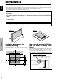
English Installation You can attach your optional mounts or stand to the plasma monitor in one of the following two ways: * While it is upright. (See Drawing A) * As it is laid down with the screen face down (See Drawing B). Lay the protective sheet, which was wrapped around the monitor when it was packaged, beneath the screen surface so as not to scratch the screen face. * Do not touch or hold the screen face when carrying the unit. • This device cannot be installed on its own.
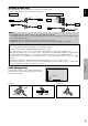
Creating a video wall English With built-in matrix display capability, you can create a 4-25 video wall. • Connect signal cables and remote cables as shown below. Video signal PC/COMPONENT signal BNC connector BNC connector VIDEO signal Remote control IN OUT VIDEO signal RCA phono plug PC signal / IN COMPONENT signal OUT PC signal / COMPONENT signal OUT Remote control IN OUT Remote control Remote control IN Note: 1. The VIDEO1 and PC1 terminals can be used for either INPUT or OUTPUT.
English Caution on when the plasma monitor is installed vertically • Use the optional unit. Contact your store of purchase when installing. • Rotate 90° clockwise as seen from the front when installing. • After installing, check with the PIONEER logo mark as seen from the front. • Be sure to set “OSD ANGLE” to “V” when using. * Failure to heed the above cautions may lead to malfunction.
Part Names and Function English Front View 6 5 q Power ( ) Turns the monitor’s power on and off. w Remote sensor window Receives the signals from the remote control. e STANDBY/ON indicator When the power is on ............................. Lights green. When the power is in the standby mode ... Lights red. r INPUT/EXIT Switches the input. The available inputs depend on the setting of “BNC INPUT”, “RGB SELECT” and “DVI SET-UP”. Functions as the EXIT buttons in the On-Screen Display (OSD) mode.
Part Names and Function English Rear View/ Terminal Board A AC IN Connect the included power cord here. B EXT SPEAKER L and R Connect speakers (optional) here. Maintain the correct (positive) speaker wire to the polarity. Connect the EXT SPEAKER terminal and the (negative) speaker wire to the EXT SPEAKER terminal on both LEFT and RIGHT channels. Please refer to your speaker’s owner’s manual. C VIDEO1, 2, 3 (BNC, RCA, S-Video) Connect VCR’s, DVD’s or Video Cameras, etc. here.
q POWER ON/STANDBY Switches the power on/standby. (This does not operate when STANDBY/ON indicator of the main unit is off.) w RGB/PC Press this button to select RGB/PC as the source. RGB/PC can also be selected using the INPUT/EXIT button on the monitor. e COMPONENT Press this button to select COMPONENT as the source. COMPONENT can also be selected using the INPUT/ EXIT button on the monitor. r VIDEO Press this button to select VIDEO as the source.
English Basic Operations POWER OFF TIMER To turn the unit ON and OFF: 1. Plug the power cord into an active AC power outlet. 2. Press the Power button (on the unit). The monitor’s STANDBY/ON indicator turns red and the standby mode is set. 3. Press the POWER ON button (on the remote control) to turn on the unit. The monitor’s STANDBY/ON indicator will light up (green) when the unit is on. 4. Press the POWER STANDBY button (on the remote control) or the Power button (on the unit) to turn off the unit.
WIDE Operations 2.35:1 size screen With this function, you can select one of six screen sizes. When viewing videos or digital video discs 1. Press the SCREEN SIZE button on the remote control. 2. Within 3 seconds ... Press the SCREEN SIZE button again. The screen size switches as follows: → 4:3 → FULL → WIDE → ZOOM → 2.35:1 → 14:9 When a 720P or 1080I signal is input: FULL ↔ 2.35:1 4:3 size screen English SCREEN SIZE Operation (manual) Original image Information is lost on both sides.
English SCREEN SIZE Operation with Computer Signals Switch to the wide screen mode to expand the 4 : 3 image to fill the entire screen. 1. Press the SCREEN SIZE button on the remote control. 2. Within 3 seconds ... Press the SCREEN SIZE button again. The screen size switches as follows: → 4:3 → FULL → ZOOM 4:3 size screen (4:3 or SXGA 5:4) The picture has the same size as the normal computer image. FULL size screen The image is expanded in the horizontal direction.
Menu Operations The OSD window is displayed with respect to the screen as shown on the diagram. * Depending on the screen’s mode, the OSD may be displayed differently. In the explanation, the OSD section is shown close up. 1/2 MAIN MENU PICTURE SOUND SCREEN OPTION1 ADVANCED OSD NEXT PAGE SEL. MENU OK : OFF EXIT EXIT The following describes how to use the menus and the selected items. 1. Press the MENU/SET button on the remote control to display the MAIN MENU.
English Menu Tree :Shaded areas indicate the default value. ←→ : Press the or button to adjust. :Menu items in a ruled box are available when the ADVANCED OSD is set to ON. Main menu Sub menu Sub menu 2 PICTURE CONTRAST BRIGHTNESS SHARPNESS COLOR TINT AV SELECTION DNR COLOR TEMP. WHITE BALANCE ←→ 0←52→72 ←→ 0←32→64 ←→ 0←16→32 ←→ 0←32→64 R←→G 0←32→64 DYNAMIC/STD/MOVIE1/MOVIE2/DEFAULT OFF/LOW/MID/HIGH LOW/MID LOW/MID/HIGH R.HIGH ←→ 0←40→70 G.HIGH ←→ 0←40→70 B.HIGH ←→ 0←40→70 R.
Sub menu 2 PWR. MGT. PURECINEMA LONG LIFE OFF←→ON OFF←→ON ABL ORBITER SIDE MASK S1/S2 DVI SET-UP Sub menu 4 AUTO/LOCK 1/LOCK 2/LOCK 3 AUTO 1 AUTO 2 MANUAL H-DOT/V-LINE/TIME OFF INVERSE OFF ON WORKING TIME/WAITING TIME WHITE SCREEN WIPER OFF ON WORKING TIME/WAITING TIME/SPEED SOFT FOCUS OFF/1/2/3/4 0←…→3←…→15 AUTO←→OFF PLUG/PLAY PC←→STB/DVD BLACK LEVEL LOW←→HIGH Main menu Sub menu Sub menu 2 OPTION3 TIMER PRESENT TIME PWR.
English Picture Settings Menu Adjusting the picture The contrast, brightness, sharpness, color and tint can be adjusted as desired. Example: Adjusting the contrast On “CONTRAST” of “PICTURE” menu, adjust the contrast. 1/2 PICTURE CONTRAST BRIGHTNESS SHARPNESS COLOR TINT : STD AV SELECTION : OFF DNR NEXT PAGE SEL. EXIT RETURN ADJ. 52 CONTRAST OSD (On Screen Display) Controls Note: If “CAN NOT ADJUST” appears ... When trying to enter the PICTURE submenu, make sure AV SELECTION is not set to DEFAULT.
Making the Low Tone adjustments This feature allows more detailed tone to be reproduced especially in the dark area. Example: Setting “2” Set “ADVANCED OSD” to “ON” in the MAIN MENU (1/2), then perform the following operations. On “LOW TONE” of “PICTURE” menu, select “2”. PICTURE PREVIOUS PAGE COLOR TEMP. : GAMMA : LOW TONE : C.DETAIL ADJ. English Adjusting the color to the desired level Use this procedure to adjust the white balance for each color temperature to achieve the desired color quality.
English SOUND Settings Menu SCREEN Settings Menu Adjusting the treble, bass and left/right balance and audio input select The treble, bass and left/right balance can be adjusted to suit your tastes. Example: Adjusting the bass Adjusting the Position, Size, PHASE, CLOCK The position of the image can be adjusted and flickering of the image can be corrected. Example: Adjusting the vertical position in the normal mode On “BASS” of “SOUND” menu, adjust the bass. On “V.
On “OPTION1” menu, select “OSD”, then press the MENU/ SET button. The “OSD” menu appears. On “DISPLAY OSD” of “OSD” menu, select “OFF”. OSD DISPLAY OSD OSD ADJUST OSD ANGLE OSD ORBITER OSD CONTRAST SEL. : : : : : ADJ. OFF 1 H OFF LOW EXIT RETURN Information DISPLAY OSD settings ON: The informations on screen size, volume control, etc. will be shown. OFF: The informations on screen size, volume control, etc. will not be shown. The DISPLAY button on the remote control will not function either.
English WIDE1: When an 852 dot 480 line signal with a horizontal frequency of 31.7kHz is input, the image may be compressed horizontally. To prevent this, set RGB SELECT to WIDE1. WIDE2: When an 848 dot 480 line signal with a horizontal frequency of 31.0 kHz is input, the image may be compressed horizontally. To prevent this, set RGB SELECT to WIDE2. WIDE3: When an 1920 dot 1200 line signal with a horizontal frequency of 74.0 kHz is input, the image may be compressed horizontally.
2/3 OPTION2 PREVIOUS PAGE PWR. MGT. : ON PURECINEMA : ON LONG LIFE SIDE MASK : 3 S1/S2 : OFF DVI SET-UP NEXT PAGE EXIT RETURN SEL. ADJ. Information Power management function * The power management function automatically reduces the monitor’s power consumption if the computer’s keyboard or mouse is not operated for a certain amount of time. This function can be used when using the monitor with a computer.
English ORBITER Use this to set the picture shift. Example: Setting “ORBITER” to “AUTO1” On “ORBITER” of “LONG LIFE” menu, select “AUTO1”. ABL ORBITER INVERSE SCREEN WIPER SOFT FOCUS SEL. LONG LIFE : : : : : ADJ. INVERSE Use this to set the inverse mode or to display a white screen. Example: Setting “INVERSE” to “WHITE” On “INVERSE” of “LONG LIFE” menu, select “WHITE”.
On “SCREEN WIPER” of “LONG LIFE” menu, select “ON”. ABL ORBITER INVERSE SCREEN WIPER SOFT FOCUS SEL. LONG LIFE : : : : : ADJ. AUTO OFF OFF ON OFF EXIT RETURN Information SCREEN WIPER ON: The white vertical bar appears. You can set the time by pressing the MENU/SET button while “ON” is set. OFF: Screen wiper mode does not function. Setting the time for SCREEN WIPER Set a time duration and the speed.
English Setting the screen size for S1/S2 video input If the S-video signal contains screen size information, the image will be automatically adjusted to fit the screen when this S1/S2 is set to AUTO. This feature is available only when an S-video signal is input via the VIDEO3 terminal. Example: Setting “S1/S2” to “AUTO” Set “ADVANCED OSD” to “ON” in the main menu (1/ 2), then perform the following operations. On “S1/S2” of “OPTION2” menu, select “AUTO”.
On “PROGRAM” of “TIMER” menu, select “ON”, then press the MENU/SET button. The “PROGRAM TIMER” screen appears. Adjust the items. Each mode switches each time the ZOOM / button is pressed. PROGRAM TIMER ON OFF INPUT FUNCTION DATE INVERSE PC2 MON 08 : 30 10 : 30 — --:-— --:-— — — --:---:-— — — --:---:-— — --:---:-— — — --:---:-— — — --:---:-— — EXIT RETURN SEL. ZOOM ADJ. Information PROGRAM TIMER settings DATE: Set the day of the week (e.g. Sunday).
English Enabling/disabling remote control wireless transmission This function enables/disables remote control wireless transmission. Example: Setting “OFF” Set “ADVANCED OSD” to “ON” in the main menu (1/ 2), then perform the following operations. On “IR REMOTE” of “OPTION3” menu, select “OFF”, then press the MENU/SET button. OPTION3 PREVIOUS PAGE TIMER PWR. ON MODE : KEY LOCK : IR REMOTE : LOOP OUT : ID NUMBER : VIDEO WALL SEL. ADJ.
On “DIVIDER” of “VIDEO WALL” menu, select “4”. DISP. MODE Select the screen mode from between two options (NORMAL, ADJUST). Example: Setting “ADJUST” On “DISP. MODE” of “VIDEO WALL” menu, select “ADJUST”. Information DIVIDER settings OFF, 1: 1 Screen (Matrix display function does not work) 4: 4 Screens (2×2 video wall) 9: 9 Screens (3×3 video wall) 16: 16 Screens (4×4 video wall) 25: 25 Screens (5×5 video wall) * When you select 4-25, set the VIDEO WALL POSITION.
English SCREEN The position of the image can be adjusted and flickering of the image can be corrected. Example: Adjusting the vertical position On “VIDEO WALL” menu, select “SCREEN”, then press the MENU/SET button. The “SCREEN” screen appears. On “V.POSITION” of “SCREEN” menu, adjust the position. SCREEN SCREEN SIZE : 4:3 V.POSITION H.POSITION V.SIZE H.SIZE AUTO PICTURE : OFF PHASE CLOCK SEL. EXIT RETURN ADJ. V.POSITION P. ON DELAY (Power on delay) Use this function to activate power-on delay.
1 DIVIDER SOURCE WORK TIME : : : ADJ. 4 PC1DSUB 00H06M EXIT RETURN Advanced OSD Settings Menu Setting the menu mode This allows you to access full menu items. When P. ON DELAY or ABL LINK is ON, this won’t be turned OFF. Example: Setting “ON” On “ADVANCED OSD” of “MAIN MENU”, select “ON”. 1/2 MAIN MENU ADVANCED OSD NEXT PAGE SEL. ADJ. : OFF EXIT EXIT MAIN MENU PICTURE SOUND SCREEN OPTION1 OPTION2 OPTION3 ADVANCED OSD : ON NEXT PAGE EXIT EXIT SEL. ADJ.
English Pin Assignments mini D-Sub 15-pin connector (Analog) PC 1 DVI-D 24-pin connector (Digital) The unit is equipped with a type of connector commonly used for digital. (This cannot be used for an analog input.) (TMDS can be used for one link only.) 5 4 3 2 1 10 9 8 7 6 15 14 13 12 11 Pin Assignments Pin No.
Table of Signals Supported Supported resolution Computer input signals supported by this system Model Dots lines Signal Type 640 400 640 480 848 480 852 480*1 800 600 IBM PC/AT compatible computers*8 1024 768 1152 864 1280 768 1280 768*9 1280 800*9 1280 854*9 1360 765 1360 768 1376 768 1280 1024 1680 1050*9 1600 1200 1920 1200*9 1920 1200RB*9 640 480 Apple Macintosh*6, 832 624 *8 1024 768 1152 870 1440 900*9 Work Station 1280 1024 (EWS4800)*8 Work Station (HP)*8 1280 1024 Work Station 1152 900 (S
English *1 Only when using a graphic accelerator board that is capable of displaying 852 480. *2 Display only 400 lines with the screen center of the vertical orientation located at the center. *3 The picture is displayed in the original resolution. The picture will be compressed for other signals. *4 Aspect ratio is 5:4. This signal is converted to a 600 dots 480 lines signal. *5 Normally the RGB select mode suite for the input signals is set automatically.
Troubleshooting Picture is disturbed. Sound is noisy. Remote control operates erroneously. The remote control does not work. Monitor’s power does not turn on when the remote control’s power button is pressed. Checks • If there are no abnormalities in the image and sound, the noise is caused by the cabinet reacting to changes in temperature. This will not affect performance.
Specifications Aspect Ratio Resolution Signals Synchronization Range Specifications Input Signals 32 En 36.3"(H) 20.4"(V) inches 921(H) 518(V) mm diagonal 42" 16 : 9 853(H) 480(V) pixels Horizontal : 15.5 to 110 kHz (automatic : step scan) Vertical : 50.0 to 120 Hz (automatic : step scan) RGB, NTSC (3.58/4.