Plasma Display Écran à plasma プラズマディスプレイ PDP-503CMX PDP-433CMX Contents related to system specifications, power requirements, accessories, and other information differ with respect to the country where this unit is purchased. For customers living in the U.S.A. or Canada, please use and refer to the instructions written in either English or French. For customers in Japan, please use and refer to the instructions written in Japanese.
English This unit has been designed for use as a computer display monitor. The optional video card is required if you wish to view other video signals on the monitor. For details consult your local retail dealer. Français Cet appareil est conçu pour une utilisation comme moniteur d’affichage d’ordinateur. La carte vidéo optionnelle est nécessaire si vous souhaitez regarder d’autres signaux sur ce moniteur. Pour plus de renseignements, consultez votre revendeur.
English Français Operating Instructions Thank you very much for purchasing this PIONEER product. Before using your Plasma Display, please read the “Safety Precautions” and these “Operating Instructions” carefully so you will know how to operate the Plasma Display properly. Keep this manual in a safe place. You will find it useful in the future. Notes on Installation Work: Safety Precautions This product is marketed assuming that it is installed by qualified personnel with enough skill and competence.
English Safety Precautions The following symbols are found on labels attached to the product. They alert the operators and service personnel of this equipment to any potentially dangerous conditions. IMPORTANT NOTICE The serial number for this equipment is located on the rear panel. Please write this serial number on your enclosed warranty card and keep it in a secure area. This is for your security.
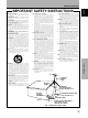
VENTILATION — Slots and openings in the cabinet are provided for ventilation and to ensure reliable operation of the product and to protect it from overheating, and these openings must not be blocked or covered. The openings should never be blocked by placing the product on a bed, sofa, rug, or other similar surface. This product should not be placed in a built-in installation such as a bookcase or rack unless proper ventilation is provided or the manufacturer’s instructions have been adhered to.
English Safety Precautions FEDERAL COMMUNICATIONS COMMISSION DECLARATION OF CONFORMITY This device complies with part 15 of the FCC Rules. Operation is subject to the following two conditions: (1) This device may not cause harmful interference, and (2) this device must accept any interference received, including interference that may cause undesired operation.
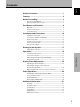
English Contents Safety Precautions ........................................................ i Features ........................................................................ 2 Before Proceeding ........................................................ 3 How to Use This Manual ................................................................ 3 Checking Supplied Accessories ..................................................... 5 Part Names and Functions ..........................................
Before Proceeding English Features PDP-503CMX PDP-433CMX ¶ Introduces newly developed 50" XGA Wide Plasma Panel ¶ Introduces newly developed 43" Wide Plasma Panel The new wide high-precision XGA 50" plasma panel (1280x768 / 16:9) pushes the envelope of previous high-luminance panels, producing brighter, clearer images with higher contrast.
How to Use This Manual This manual is set up to follow the course of actions and operations in the order that would seem most logical for someone setting up this unit. Screen Displays The example screen displays provided in this manual are those for the PDP-503CMX model.
English Before Proceeding About operations in this manual Operations in this manual are outlined in step by step numbered procedures. Most of the procedures are written in reference to the remote control unit unless the button or control is only present on the main unit. However, if a button or control on the main unit has the same or similar name as that on the remote control unit, that button can be used when performing operations.
Checking Supplied Accessories English Before Proceeding 7 Display stands (x 2) Check that the following accessories were supplied. 1 Power cord 8 Washers (x 2) 2 Remote control unit 9 Hex hole bolts (x 2) 3 AA (R6) batteries (x 2) 0 Remote control unit holder Before Proceeding Use as a holder for the remote control unit. When attaching to the rear of the main unit, be careful not to cover the vents.
English Part Names and Functions Main Unit Operation panel on the main unit 4 Main unit 5 6 7 8 3 9 0 1 2 Note Part Names and Functions When optional speakers have been connected, the operation panel on the main unit will not be operable. Main unit 1 Display stand 2 Remote control sensor Point the remote control toward the remote sensor to operate the unit (page 8).
English Part Names and Functions Remote Control Unit 1 SCREEN SIZE button Press to select the screen size (page 21). 1 2 INPUT buttons 7 Use to select the input (page 19). 8 2 3 MENU button 9 Press to open and close the on-screen menu (pages 17 to 30). 4 ADJUST (5/∞/3/2) buttons 3 Use to navigate menu screens and to adjust various settings on the unit. Usage of cursor buttons within operations is clearly indicated at the bottom the on-screen menu display (pages 17 to 30).
English Part Names and Functions Operating range of the remote control unit Connection Panel When operating the remote control unit, point it at the remote sensor (Î) located on the front panel of the main unit. The remote control unit is operable up to 23 feet (7 m) from the unit and within a 30 angle on each side of the sensor. The connection panel is provided with two video input jacks and one video output jack.
English Part Names and Functions Illustration depicts PDP-503CMX model. AC INLET 8Ω ~16Ω SPEAKER + - 8Ω ~16Ω SPEAKER + – 1 CONTROL IN OUT 2 COMBINATION IN 3 INPUT1 RS-232C OUT 4 8 Synchronizing signal impedance selector switch Depending on the connections made at INPUT2, it may be necessary to set this switch to match the output impedance of the connected component’s synchronization signal.
English Installation and Connections Installation of the Unit 3 Fix this unit using the supplied washer and bolt. Installation using the supplied display stand Be sure to fix the supplied stand to the installation surface. Use commercially available M8 bolts that are 25 mm longer than the thickness of the installation surface. 1 Fix the supplied stand to the installation surface at each of the 4 prepared holes using commercially available M8 bolts . Use a 6 mm hex wrench to bolt them.
Wall-mount installation of the unit This unit has been designed with bolt holes for wall-mount installation, etc. The installation holes that can be used are shown in the diagram below. ÷ Please be sure to request installation or mounting of this unit or the installation bracket by an installation specialist or the dealer where purchased. ÷ When installing, be sure to use the bolts provided with the stand or installation bracket.
English Installation and Connections Connection to INPUT1 and INPUT2 The INPUT 1 and INPUT 2 jacks are used to connect the display to a computer. After making the connections, adjust the screen settings in accordance with the computer’s signal output. See pages 17-18 for information regarding settings. Output source INPUT2 jack Personal computer (PC) with RGB output [ON SYNC] G G ON SYNC B R [H/V SYNC] HD Connection method differs depending on the computer type.
When connecting to INPUT1 Connection of G ON SYNC analog RGB source Make G ON SYNC connections for a personal computer with output that has the synchronization signal layered on top of the green signal. INPUT1 ANALOG RGB OUTPUT (ANALOG RGB) English Installation and Connections Français When connecting to INPUT1 INPUT1 OUTPUT (ANALOG RGB) ANALOG RGB Connect the cable corresponding to the shape of the input terminal on this unit and the personal computer’s output terminal.
English Installation and Connections Connection of composite SYNC analog RGB source Audio Connections Make composite SYNC connections for a personal computer with output that has the vertical synchronization signal layered on top of the horizontal synchronization signal. Before making connections, be sure to check that the audio component’s power and the unit’s main power is off.
English Installation and Connections Power Cord Connection When control cord connections are made, remote control operation of connected PIONEER components that bear the Î logo mark is done through the remote sensor on this unit. When the connection is made to the CONTROL IN jack on another unit, the remote sensor of that component will no longer receive signals. Point the remote control unit of the connected component at the remote control sensor on this unit to control.
English Installation and Connections How to Route Cables Speed clamps and bead bands are included with this unit for bunching cables together. Once components are connected, follow the following steps to route cables. * As viewed from the rear of the display. 1 2 Installation and Connections 1 Organize cables together using the provided speed clamps. Insert 1 into an appropriate hole on the rear of the unit, then snap 2 into the back of 1 to fix the clamp.
6 Setup after Connection English Setting Up the System Press 5/∞ to select SETTING, then press SET. MAIN MENU PICTURE After components have been connected to INPUT1 or INPUT2, on-screen setup is necessary. Follow the procedure described below and make settings as they apply to the type of components connected.
English Setting Up the System CLAMP POSITION setup 4 Press SET to select LOCKED. MAIN MENU Depending on the signal, analog RGB signals may result in the screen image appearing with a whitish or greenish cast. In such cases, set “CLAMP POSITION” to LOCKED. ÷ Normally, leave this setting at AUTO.
3 Selecting an Input Source This section explains the basic operation of this unit. Outlined on the following pages is how to turn the main power on and off, put this unit in the operation or standby mode and how to select connected components. English Operations Press INPUT on the remote control unit or the main unit to select the input. Input changes each time the main unit’s INPUT is pressed as follows.
English Operations To adjust the volume To confirm display settings DISPLAY VOLUME +/– Press VOLUME on the remote control unit. Use VOLUME + or VOLUME – to adjust the volume of the connected speakers. Press DISPLAY on the remote control unit. The currently selected input, screen size and refresh rates will be displayed for about 3 seconds. I NPUT 1 Operations V O L U ME : 5 fH: fV: To mute the sound 3 1. 5 kH z 60.
During personal computer signal input This unit incorporates screen modes of various height and width ratios. For optimal viewing, we recommend that you select the screen mode that best matches the video source that you are viewing. Although these modes are designed for full display of a picture on a wide screen, it is our hope that you make use of them with a full understanding of the manufacturer’s intentions.
English Operations 4 PARTIAL (*Supported only on PDP-503CMX) The PARTIAL setting is available only during personal computer input (1280 x 1024/60 Hz only). The input signal and the screen maintain a dot to line ratio of 1:1. Display is highly faithful to the source. However, in order to maintain the 1:1 ratio, a portion of the display will not appear on the screen. 768 lines 1024 lines Use 5/∞ to adjust the position of the video image on the screen.
Partial Image Enlargement (POINT ZOOM) 2 Press 5/∞/2/3 as required to select the desired screen area (AREA 1 to AREA 9). 3 Press SET to select the zoom ratio. Pressing SET repeatedly changes the zoom ratio in the following order: This display allows any one of nine screen areas (AREA 1 to AREA 9) to be selected and enlarged to x1.5, x2, x3, or x4. When performing point zoom enlargement, the direction buttons (5/∞/2/3) can be used to move the enlarged portion up-down and right-left.
English Operations 3 Automatic Power OFF This display is equipped with automatic powermanagement and auto-power-off functions, which allow the unit to automatically switch to power-saving mode when no sync signal is detected. (A warning message appears onscreen before these functions operate.) Press 5/∞ to select either the POWER MANAGEMENT or AUTO POWER OFF mode.
Adjusting the Picture Quality Press MENU to display the menu screen. MAIN MENU PICTURE INPUT1 SCREEN : 0 : 0 : +60 : +60 : +60 : 0 : 0 SET UP OPTION CO NT RA S T BR I GHT . R. L E V E L G. L E V E L B. L E V E L H . E NH AN CE V . E NH AN CE RE S E T SELECT 2 SET ENTER MENU EXIT Press 5/∞ to select the adjustment item, then press SET. MAIN MENU INPUT1 PICTURE SCREEN : CO NT RAS T 0 : B R I GHT . 0 : +60 R. L E V E L : +60 G. L E V E L : +60 B. L E V E L : 0 H . E NH AN CE : V .
English Display Panel Adjustments Adjusting the Image Position and Clock (Automatic Adjustment) Pressing AUTO SET UP on either the display or the remote control unit will adjust the screen position and clock to optimum values. Note Perform this adjustment individually for each input function (INPUT 1, INPUT 2), and each signal type. Display Panel Adjustments AUTO SET UP AUTO SET UP Main Unit Operating Panel Remote Control Unit Press AUTO SET UP on either the main unit or remote control unit.
1 Press MENU to display the menu screen. MAIN MENU INPUT1 PICTURE SCREEN : CO NT RA S T 0 : BR I GHT . 0 : +60 R. L E V E L : +60 G. L E V E L : +60 B. L E V E L : 0 H . E NH AN CE : V . E NH AN CE 0 SET UP OPTION RE S E T SELECT 2 SET ENTER EXIT MENU Press 2/3 to select SCREEN. MAIN MENU PICTURE INPUT1 SCREEN : POS I T I ON CL OC K / P HA S E : SET UP 0 / 0 / OPTION 0 0 RE S E T SELECT 3 SET ENTER EXIT MENU Press 5/∞ to select the adjustment item, then press SET.
English Other Operations 5 Rewriting the Input Display (INPUT LABEL) Press 2/3/5/∞ to select the first desired character (here, “C”), then press SET to confirm (repeat this step to input up to eight desired characters.) MAIN MENU This function allows rewriting of the screen contents displayed with differing inputs. For example, the default “INPUT 1” can be changed to “COMPUTER” or other name describing the connected component (up to maximum of 8 characters).
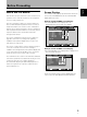
English Other Operations Power Control Function AUTO FUNCTION The power control function allows screen brightness to be suppressed as a means of lowering power consumption and reducing display deterioration. This display is equipped with an optional AUTO FUNCTION selector. When enabled, the selector automatically switches the display’s input source to INPUT 1 when an image signal is detected at the INPUT 1 jack. 1 Press MENU to display the menu screen. The menu will be displayed.
English Other Operations 4 Press SET to select INPUT 1. The factory default setting is OFF. Each time SET is pressed the selector function switches alternately as shown: 2 Press 2/3 to select OPTION. MAIN MENU PICTURE INPUT1 SCREEN SET UP OPTION POWE R C O N T R O L : S T A ND A RD A U T O F U N C T I O N : OF F : F I X ED A UD I O O U T 3 OFF INPUT1 2 5 ÷ When OFF is selected, AUTO FUNCTION is disabled.
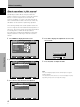
Cleaning Troubleshooting What may at first seem to be an malfunction, may be remedied with a quick check. Please check to see if a warning is displayed on the screen. If displayed, refer to the table below and check the mode. If there is no display check to see if the problem is listed on page 32. The problem may also be caused by something other than this unit so please also check the other components being used such as a video deck.
English Additional Information General problems Problem • No power • Unit cannot be operated. • Remote control does not operate. • INPUT is not changed. • Picture is cut off. • Strange color, light color, or dark, or color misalignment • Power is suddenly turned off. Additional Information • No picture Possible Solution • Is the power cord disconnected? (page 15) • Has the MAIN POWER switch been switched on? (page 9) • External influences such as lightning, static electricity, etc.
Note In order to protect the panel and internal circuitry, this display is provided with a cooling fan designed to turn on/off and change speed automatically in accordance with ambient temperature conditions (the fan sound will change in accordance with its speed). Additional cautions • If the power is automatically turned off during operation of this unit, the following reasons may be the cause. 1 Is the POWER MANAGEMENT or AUTO POWER OFF function set to ON? (page 24).
English Additional Information Specifications INPUT 2 Input General (PDP-503CMX) Light emission panel ............ 50 inch plasma display panel Number of pixels .............................................. 1280 x 768 Power supply ............................. AC 100 - 120 V, 50/60 Hz Rated current ................................................. 3.8 A - 3.1 A Standby power consumption ...................................... 1 W External dimensions ........ 1218 (W) x 714 (H) x 98 (D) mm ..............
Supplement 1 English Additional Information -1/2: PDP-503CMX : Not available. PC signal compatibilty table (INPUT1, INPUT2) Refresh rate Resolution (Dot x Line) Vertical Horizontal 640x400 56.4Hz 24.8kHz Remarks 70.1Hz 60Hz 31.5kHz 31.5kHz 800 x600 66.7Hz 72.8Hz 75Hz 85Hz 56Hz 35.0kHz 37.9kHz 37.5kHz 43.3kHz 35.2kHz 832x624 60Hz 72Hz 75Hz 85Hz 74.6Hz 37.9kHz 48.1kHz 46.9kHz 53.7kHz 49.7kHz 852x480 60Hz 31.7kHz 1024x768 60Hz 48.4kHz 1152x864 70Hz 75Hz (74.9Hz) 85Hz 60Hz 56.
English Additional Information Supplement 1 -2/2: PDP-433CMX : Not available. PC signal compatibilty table (INPUT1, INPUT2) Refresh rate Resolution (Dot x Line) Vertical Horizontal 640x400 56.4Hz 24.8kHz Screen size (Dot x line) Remarks 640x480 70.1Hz 60Hz 31.5kHz 31.5kHz 800 x600 66.7Hz 72.8Hz 75Hz 85Hz 56Hz 35.0kHz 37.9kHz 37.5kHz 43.3kHz 35.2kHz 832x624 60Hz 72Hz 75Hz 85Hz 74.6Hz 37.9kHz 48.1kHz 46.9kHz 53.7kHz 49.7kHz 852x480 60Hz 31.7kHz 1024x768 60Hz 48.
Supplement 2 Explanation of Terms Signal assignment of INPUT 1 (Mini D-sub 15 pin socket connector) Aspect ratio 5 1 English Additional Information The TV screen’s width to height ratio is referred to as its aspect ratio. The aspect ratio on standard TVs is 4:3 and on wide TVs or High Definition TVs it is 16:9. G ON SYNC This indicates a video signal in the form of a synchronization signal added to the G (GREEN) signal of the R.G.B signal. 6 VGA 15 11 Pin No.
Published by Pioneer Corporation. Copyright © 2002 Pioneer Corporation. All rights reserved.