PDP-504CMX Plasma Display Panel RS-232C Commands COMMAND PROTOCOL MANUAL Manual Version 1.00 November 3, 2004 Pioneer Corporation Pioneer Electronics (USA) Inc.
This manual is copyrighted with all rights reserved. No part of this document may be reprinted, produced, translated or utilized in any form or by any means now known or hereafter invented including, but not limited to, any electronic, mechanical, photocopying and recording or information storage and retrieval system means, without the express written permission from Pioneer Electronics (USA) Inc. Every effort has been made to ensure that the information in this manual is accurate.
RS-232C Adjustment Mode 5.5 RS-232C Adjustment Mode This display has a RS-232C terminal. It is possible to use a PC to make various adjustments and settings. 5.5.1 About the RS-232C Adjustment Mode 1) Adjustments in the RS-232C adjustment mode: • The adjustments are written to the same memory area as for the integrator mode (refer to section 5.4.4, ‘PICTURE, White Balance and SCREEN Position Adjustment Values Memory Area Tables’).
RS-232C Adjustment Mode 5.5.2 Interface 1) Connector D-sub 9 pins (male) 2) Pin layout Pin No. 1 2 3 4 5 1 Signal NC (not connected) TxD (Transmit Data) RxD (Receive Data) NC (not connected) GND Pin No. 6 7 8 9 5 Signal NC (not connected) NC (not connected) RTS (Request To Send) NC (not connected) 6 9 3) Baud Rate 9600 bps (standard) (switch-able to 1200, 2400, 4800, 19200, 38400 bps) Note The baud rate of this display should be set to match the baud rate of the PC.
RS-232C Adjustment Mode 5.5.3 ID Assignment After connecting to the PC, an ID is assigned. The ID is assigned from the PC. Commands: (ID CLEAR) ........ Clears the assigned ID (ID SET) ............. Assigns an ID IDS is only effective when an ID is not assigned. Also, IDs are set starting from the set closest to the PC.
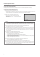
RS-232C Adjustment Mode 5.5.4 Combination Connection When performing control and adjustment, it is convenient to connect several sets to one PC. By performing a combination connection and assigning IDs to the sets, it is possible to control and adjust several sets at the same time or separately. Connection method: Connect the sets as shown in the figure below, and perform control and adjustment with the PC.
RS-232C Adjustment Mode Under the connection conditions shown below, operation using a combination cable is assured up to 16 sets. Conditions: 1 Length of RS-232C cable connecting PC to PDP-504CMX/PDP-50MXE1/PDP-50MXE1-S: 5 m 2 Combination cable length: 5 m each 3 Wire specifications for linking cable: Mini Din 6-pin straight (7 strand cable) For 1 strand, suitable for AWG28: Cross-section area = 0.08 mm2 ≠ 7 strands × π r2 = 7 × 3.14 × 0.062 = 0.079 mm2 ≠ 0.
RS-232C Adjustment Mode 5.5.5 List of RS-232C Commands How to read this Table • RS-232C adjustment validity : Indicates whether or not the RS-232C adjustment mode can be used. • Normal validity : Indicates whether or not the normal-operation mode can be used. • Numerical direct validity : When a number (3-digit number) is attached to the end of a command, the command can directly set that adjustment value. • ‡ or ¶: Valid, No mark: Invalid (NOTE) ¶ values are not stored in the last memory.
RS-232C Adjustment Mode Command name AJY (232C integrator) Display Remarks CTR CTI: ### Displays the current CTI setting. CTRS00 CTI: OFF Sets CTI to OFF. CTRS01 CTI: ON Sets CTI to ON. DIY OSD: ON Turns ON the OSD display. DNR DNR: ###### Displays the current DNR setting. DNRS00 DNR: OFF Sets digital NR to ON. DNRS01 DNR: LOW Sets digital NR to LOW. DNRS02 DNR: MIDDLE Sets digital NR to MIDDLE. DNRS03 DNR: HIGH Sets digital NR to HIGH.
RS-232C Adjustment Mode Command name Remarks AJY (232C integrator) Display GRA GRADATION: ####### Displays the current GRADATION setting GRAS01 GRADATION: GAMMA 2.0 Sets GRADATION to ‘GAMMA 2.0’. GRAS02 GRADATION: GAMMA 1.8 Sets GRADATION to ‘GAMMA 1.8’. GRAS03 GRADATION: GAMMA 2.2 Sets GRADATION to ‘GAMMA 2.2’. GRAS04 GRADATION: DRE MID Sets GRADATION to ‘DRE MID’. GRAS05 GRADATION: DRE HIGH Sets GRADATION to ‘DRE HIGH’. GRAS06 GRADATION: DRE LOW Sets GRADATION to ‘DRE LOW’.
RS-232C Adjustment Mode Command name Remarks AJY (232C integrator) Display MIR MIRROR MODE: ### Displays the current MIRROR MODE setting. MIRS00 MIRROR MODE: OFF Turns the MIRROR MODE OFF (normal display). MIRS01 MIRROR MODE: X Sets the MIRROR MODE to left-right reversal. MIRS02 MIRROR MODE: Y Sets the MIRROR MODE to up-down reversal. MIRS03 MIRROR MODE: XY Sets the MIRROR MODE to up-down, left-right reversal. MNR MPEG NR: ###### Displays the current MPEG NR setting.
RS-232C Adjustment Mode Command name AJY (232C integrator) Display Remarks SSI ######### Displays the current sub screen input function. SSIS01 INPUT1(SUB) Switches the sub screen to INPUT1. SSIS02 INPUT2(SUB) Switches the sub screen to INPUT2. SSIS03 INPUT3(SUB) Switches the sub screen to INPUT3. SSIS04 INPUT4(SUB) Switches the sub screen to INPUT4. SSIS05 INPUT5(SUB) Switches the sub screen to INPUT5.
RS-232C Adjustment Mode 5.5.6 GET Commands What are GET commands? • They are commands for outputting TXD such as adjustment data from the internal microcomputer of the plasma display to a PC. • Adjustment data and the like is output in ASCII code. Note Command names are given inside brackets < >. • Data output format STX (02hex) Data Data ···· Data Checksum ETX (03hex) Notes • A GET command is invalid when no ID No. is assigned to the set.
RS-232C Adjustment Mode 2) (GET PICTURE DATA: Gets integrator/PICTURE data.) Order 1 2 3 4 5 6 7 8 9 10 11 12 13 14 15 16 Data contents CONTRAST BRIGHTNESS C. DETAIL R (RED) C. DETAIL Y (YELLOW) C. DETAIL G (GREEN) C. DETAIL C (CYAN) C. DETAIL B (BLUE) C. DETAIL M (MAGENTA) H.ENHANCE V.
RS-232C Adjustment Mode 5) (GET STATUS SETUP: Gets menu and integrator SETUP data.) Order Data contents 1 GRADATION Size 1 Byte 2 3 4 BRT.ENHANCE SUB VOLUME COLOR TEMP. 1 Byte 2 Byte 1 Byte 5 DNR 1 Byte 6 MPEG NR 1 Byte 7 8 CTI PURECINEMA 1 Byte 1 Byte 9 COLOR DECODING 1 Byte 10 COLOR SYSTEM 1 Byte 11 12 13 14 15 SIGNAL FORMAT Dummy data Input function data (main) Screen size data Check sum 3 Byte 3 Byte 3 Byte 1 Byte 2 Byte SIGNAL FORMAT Output 1: GAMMA 2.0 2: GAMMA 1.
RS-232C Adjustment Mode 6) (GET STATUS OPTION: Gets menu and integrator OPTION data.
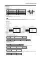
RS-232C Adjustment Mode Check Sum This is data to which 2-Byte ASCII code is added to a data group returned by a GET command. PC side STX 02 (hex) GET command ID 2 Byte ETX 03 (hex) 3 Byte Set side STX 02 (hex) GET command Check Sum Data *Byte 3 Byte 2 Byte ETX 03 (hex) A detailed example will be given below. Example: The Check Sum value that is added when the GET command GAA returned the following 6-Byte data.
PDP-504CMX RS-232C Command Protocol Manual Pioneer Electronics (USA) Inc. Industrial Solutions Business Group 2265 East 220th Street Long Beach, California 90810 United States of America (310) 952-2000 http://www.pioneerelectronics.