DUCTED CONCEALED (CEILING RECESSED) MINI SPLIT SYSTEM AIR CONDITIONER/HEAT PUMP MEDIUM EXTERNAL STATIC PRESSURE TYPE RAB/RYB Series RAB: Cooling Only Version RYB Cooling and Heating Version Inverter+ and Inverter++ Models 9,000-48,000 BTU/hr Installation Manual IMPORTANT NOTICE: Please read this manual carefully before installing or operating your new air conditioning system. Be sure to save this manual for future reference.
If your indoor unit is a part of a MULTI-SPLIT system set, refer to the installation manual that is packed with your outdoor unit as well.
Table of Contents Installation Manual 1 Accessories.......................................................................05 2 Safety Precautions....................................................06 3 Installation Overview ............................................07 4 Indoor Unit Installation.......................................08 a. Indoor Unit Parts.........................................................08 b. Indoor Unit Installation Instructions............09 5 Outdoor Unit Installation........
7 Refrigerant Piping Connection...............................18 A. Notes on Pipe Length and Elevation......................18 B. Refrigerant Piping Connection Instructions .....20 L1 L2 8 Wiring...................................................................23 a. Outdoor Unit Wiring.............................23 b. Indoor Unit Wiring.................................24 c. Power Specifications.............................26 9 Air Evacuation..............................................................
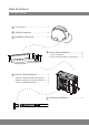
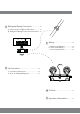
1 Accessories The air conditioning system comes with the following accessories. Use all of the installation parts and accessories to install the air conditioner. Improper installation may result in water leakage, electrical shock and fire, or equipment failure.
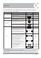
Safety Precautions 2 Read and Understand Safety Precautions Prior to Installation Improper installation due to negligence of instructions may result in serious damage or injury. The magnitude of potential damages or injuries is classified as either a WARNING or a CAUTION. WARNING Failure to observe a warning may result in death. The product must be installed by installers or contractors who are licensed HVAC professionals and in compliance with all local, state, and provincial laws.
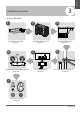
Unit Installation Overview 3 Installation Overview INSTALLATION ORDER 1 3 2 Install the Indoor Unit (Page 8) 6 Install the Outdoor Unit (Page 13) 4 5 L1 MC Install the Drainpipe (Page 15) L2 MC Evacuate the Refrigeration System (Page 26) Connect the Wires (Page 23) Connect the Refrigerant Pipes (Page 18) 7 Perform a Test Run (Page 28) Page 7
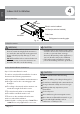
4 Indoor Unit Installation Indoor Unit Installation Indoor Unit Parts Air Inlet Electric control cabinet Air filter(on selected models) Drain hose Air Outlet Fig. 4.1 Refrigerant connecting pipe Safety Precautions WARNING • Securely install the indoor unit on a structure that can sustain its weight. If the structure is too weak, the unit may fall, causing personal injury, unit and property damage, or even death.
Installation Location >11.8in (30cm) Strong, durable ceiling >3/4 in(2cm) >4in (10cm) >12in (30cm) Service Access Ceiling (When no ceiling) B > 8’ (250cm) Right Side Left Side Floor Maintenance Space > 8 in (20cm) Air Outlet Air Inlet > 12in (30cm) 24inx24in (60cmx60cm) inspection opening Fig. 4.2 Step 2: Hang the Indoor Unit. 1. Please refer to the following diagrams to locate the four positioning screw bolt holes on the ceiling.
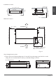
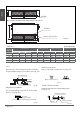
Air Inlet dimensions Indoor Unit Installation Air Filter Descending Ventilation Opening and Mounted Hook Air Filter Electric Control Box Fig. 4.3 Table.4-1 (unit: mm/inch) Outline dimension Air Outlet Opening size MODEL (Btu/h) A B C D 9K/12K 700/27.6 200/7.9 506/19.9 450/17.7 152/6 537/21.1 18K 880/34.6 210/8.3 674/26.5 600/23.6 136/5.4 24K 1100/43.3 249/9.8 774/30.5 700/27.6 175/6.9 30K~36K 1360/53.5 249/9.8 774/30.5 700/27.6 36K~60K 1200/47.2 300/11.8 874/34.
CAUTION Shockproof Cushion 2. Install and fit pipes and wires after you have finished installing the main body.When choosing where to start, determine the direction of the pipes to be drawn out. Especially in cases where there is a ceiling involved, align the refrigerant pipes, drain pipes, and indoor and outdoor lines with their connection points before mounting the unit. 3. Install hanging screw bolts. Cut off the roof beam. Strengthen the point at which the cut was made. Consolidate the roof beam. 4.
Step 4: Adjust the air inlet direction (from rear side to under-side). Step 5: Fresh air duct installation Dimension : Indoor Unit Installation 1. Take off the ventilation panel and flange. Duct Joint for fresh air Air Return Flange MODEL 18-60 Ø125mm(5”) Ventilation Panel Ø160mm (6-1/4”) Fig. 4.11 2. Change the mounting positions of the ventilation panel and air return flange. Ventilation panel Fig. 4.
5 Outdoor Unit Installation Outdoor Unit Installation Instructions √ √ √ √ √ The area must be free of combustible gases and chemicals. The pipe length between the outdoor and indoor unit may not exceed the maximum allowable pipe length. If possible, DO NOT install the unit where it will be exposed to direct sunshine. If possible, make sure the unit is located far away from the property of neighbors, so that the unit noise will not cause disturbances.
Split Type Outdoor Unit (Refer to Fig 5.4, 5.5, 5.6, 5.10 and Table 5.1) H Fig. 5.4 Outdoor Unit Installation W W H Fig. 5.5 A D B Fig. 5.6 Table 5.1: Length Specifications of Split Type Outdoor Unit (unit: mm/inch) Outdoor Unit Dimensions WxHxD Mounting Dimensions Distance A Distance B 549 (21.6) 325 (12.8) 514 (20.24) 340 (13.39) 540 (21.26) 350 (13.8) 673 (26.5) 403 (15.87) 673 (26.5) 403 (15.87) 634 (24.96) 404 (15.9) YN009GMFI22RPD: 770x555x300 (30.3x21.9x11.
30 cm / 12” ll ck ba rom ”f 30 cm 2 /1 wa ” cm /4 , 10 ts cke ra gb sin If u on le M ft 60 cm / 24” on rig ht P 8” m 0c 20 /7 in nt fro N 2. Insert the drain joint into the hole in the base pan of the unit. 3. Rotate the drain joint 90° until it clicks into place facing the front side of the unit. 4. Connect a drain hose extension (not included) to the drain joint, to redirect water from the unit during heating mode.
6 Drainpipe Installation The drainpipe is used to drain water away from the unit. Improper installation may cause unit and property damage. CAUTION Insulate all piping to prevent condensation, which could lead to water damage. • If the drainpipe is bent, or installed incorrectly, water may leak and cause a water-level switch malfunction. • In HEAT mode, the outdoor unit will discharge water. Ensure that the drain hose is placed in an appropriate area, to avoid water damage and slippage.
3. Using a 65-mm (2.5”) core drill, drill a hole into the wall. Be sure that the hole is drilled at a slightly downward angle, so that the outdoor end of the hole is lower than the indoor end by about 12-mm (0.5”). This will ensure proper water drainage (See Fig. 6.5). Place the protective wall cuff into the hole. This protects the edges of the hole, and will help seal it once installation is completed. Units WITH a Pump. 1. Remove the test cover. Fill the water pan with 2 liters of water.
7 Refrigerant Piping Connection Safety Precautions WARNING • • Refrigerant Piping Connection • • All field piping must be completed by a licensed technician, and must comply with all relevant local and national regulations. When the air conditioner is installed in a small room, measures must be taken to prevent the refrigerant concentration in the room from exceeding the safety limit, in the event of refrigerant leakage.
CAUTION • CAUTION When the outdoor unit is installed higher than the indoor unit: Oil traps When the indoor unit is installed higher than the outdoor unit: -It is recommended that vertical suction risers not be upsized. Proper oil return to the compressor should be maintained with suction gas velocity. If velocities drop below 7.6 m/s (1500 fpm (feet per minute)), oil return will be decreased. An oil trap should be installed every 6m (20ft) of vertical suction line riser. (See Fig. 7.
Table 7.2 Permitted length Total Piping length 18K+18K 30m/98’ 24K+24K 50m/164’ L+Max (L1, L2) 30K+30K Piping Length Drop Height (farthest distance from the line pipe branch) 15m/50’ Step 1: Cut pipes When preparing refrigerant pipes, take extra care to cut and flare them properly. This will ensure efficient operation, and minimize the need for future maintenance.
PIPING EXTENSION BEYOND FLARE FORM Step 3: Flare Pipe Ends Proper flaring is essential in achieving an airtight seal. 1. After removing burrs from the cut pipe, seal the ends with PVC tape, to prevent foreign materials from entering into the pipe. 2. Sheath the pipe with insulating material. 3. Place flare nuts on both ends of pipe. Make sure that they are facing the correct direction, because they cannot be put on or have their direction changed after flaring. See Fig. 7.
NOTE: Use both a spanner and a torque wrench when connecting or disconnecting pipes to/from the unit. NOTE: DO NOT intertwine signal cable with other wires. While bundling these items together, do not intertwine or cross the signal cable with any other wiring. 7. Thread this pipeline through the wall and connect it to the outdoor unit. 8. Insulate all the piping, including the valves of the outdoor unit. 9.
8 Wiring Safety Precautions WARNING • • • • • • • CAUTION • • • • Connect the outdoor wires before connecting the indoor wires. Make sure you ground the unit. The grounding wire should be located away from gas pipes, water pipes, lightning rods, telephone wires or other grounding wires. Improper grounding may cause electrical shock. DO NOT connect the unit to the power source until all wiring and piping is completed. Make sure that you do not cross your electrical wiring with your signal wiring.
Table 8.2: Other World Regions Rated Current of Nominal Cross-Sectional Appliance (A) Area (mm²) 6 0.75 6 - 10 10 - 16 16 - 25 25- 32 32 - 45 1 1.5 2.5 4 6 b. Using wire strippers, strip the rubber jacket from both ends of the signal cable to reveal approximately 15cm (~6”) of wire. c. Strip the insulation from the ends. d. Using a wire crimper, crimp u-lugs onto the ends. NOTE: When connecting the wires, strictly follow the wiring diagram found inside the electrical box cover. 2.
CAUTION • • While connecting the wires, please follow the wiring diagram strictly. The refrigerant circuit can become very hot. Keep the interconnection cable away from the copper tube. 4. Clamp down the cable with the cable clamp. The cable must not be loose or tug on the u-lugs. - Press “CONFIRM”. The air conditioning unit will then start the fan for automatic airflow adjustment. ON will flash when the fan is on during automatic airflow adjustment. 5. Reattach the electric box cover.
9 Air Evacuation BLUE (Low Pressure) Gauge MC BLUE (Low Pressure) Side of Manifold Gauge RED (High Pressure) Gauge MC RED (High Pressure) Side of Manifold Gauge Low Pressure Valve High Pressure Valve YELLOW (Common) Side of Manifold Gauge Caution: Systems are precharged with refrigerant (entire amount necessary for the system set has been charged into the outdoor section).
Copper Pipe from Indoor Unit Open the BLUE (Low Pressure) valve of the manifold Gauge. Keep the RED (High Pressure) Valve closed. Flare Nut 4. Turn the vacuum pump ON to start evacuating the air from the line set and indoor unit circuits. 5. Run the vacuum pump for at least 15 minutes, or until the Low Pressure Gauge reads -76cmHG (-100 kPa or -30 in Hg) (negative value). 6. Close the Blue (Low Pressure) Valve of the Manifold Gauge, then turn the vacuum pump OFF. Hexagonal Dust Cap 7.
Test Run 10 Test Run f. Check to see that the drainage system is Before the Test Run unimpeded, is and draining smoothly. A test run must be performed after the entire g. Ensure there is no vibration or abnormal system has been fully installed. Confirm noise during operation. the following points prior to performing the test: 5. For the Outdoor Unit a) The indoor and outdoor units are properly a. Check to see if the refrigeration system is installed. leaking. b) Piping and wiring are properly connected.
The design and specifications are subject to change without prior notice for product improvement. Consult with the sales agency or manufacturer for details. is a registered trademark of Parker Davis HVAC International, Inc. Parker Davis HVAC International, Inc. 2250 NW 102 Place, Doral, FL 33172 - USA Tel : (305) 513-4488 Fax : (305) 513-4499 email : info@pd-hvac.com Website: www.pd-hvac.com QST2I-045AEN(I) 16123000000713 20171121 Copyright 2017, Parker Davis HVAC International, Inc.