
Instruction Manual

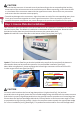
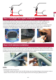
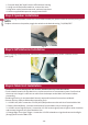
Table Of Contents

When installing the GPS Antenna, make sure it is not obstructed by any panels inside the vehicle
(see Fig 16).
Fig 16
Step 4: Speaker Installation
While installing the speaker, make sure it is not obstructed by any panels inside the vehicle
(see Fig 15).
NOTE:
To adjust volume on the speaker, toggle the switch to the desired setting, “HI/LOW/OFF”.
Fig 15
Step 5: GPS Antenna Installation
Step 6: Main Unit Installation
The Main Unit is not waterproof and must be installed securely inside the vehicle.
Find a suitable location for the Main Unit, Confirm that
the sensor wire length is sufficient to reach from the bumper to the Main Unit location before
proceeding.
Soldering all wiring is recommended. Securely tape and insulate all connections soldered.
・
・ similar to an alarm or remote start system.
・
・Secure all wires neatly to hide and prevent wire pinch.
1. +12 VDC ACC/IGN - Locate the +12 VDC (ACC/IGN) and connect the red wire from the Main Unit.
2. Chassis Ground (Black) - Connect the black wire from the Main Unit to chassis ground.
3. +12 VDC reverse signal (Green) - Locate the +12 VDC reverse signal (reverse light or other location)
and connect the green wire from the Main Unit.
4. Orange Right-Turn signal Trigger - Locate the +12 VDC Isolated turn signal and connect the Right
(Orange) wire from the Main Unit.
-14-
1. First peel back 3M® tape from the LED indicator housing.
2. Using a small flat head screwdriver, remove the cover.
3. Align wire notch from the new cover, and snap into place.
4. Use the supplied 3M tape and re-apply behind LED.
English