
Manual

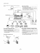

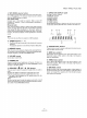


CONNECTIONS
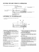
When not using the unit for a long period, disconnected the pow- _
er cord. _ M LOOP ANTENNA
A set the antenna on a level surface, and point in the direc-
tion that gives optimum reception.
• Do not install the antenna in locations where it touches the
cover of the receiver or other metal objects, or near a CD
player, personal computer, or television set.
AM loop antenna FM Antenna
/
Illustration shows
SX-303R multivoltage model.
Ground
To AC wall sockel
R
r sy
Speaker
_. R _- system B
V
Turntable CD player LD player etc. Cassette deck Cassette deck
/VCR
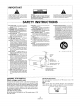
Connecting the input/output cords NOTE ABOUT SPEAKER CONNECTIONS
When another stereo component (purchased separately) is con- • Speaker systems used should have an impedance of between
nected note the following instructions. 8 Q and 16 _.
• Connect the plugs properly.Faulty connections can cause • Be sure that connections are secure. Check to make sure that
noise and also breakdowns and failures, wires do not protrude from their terminals.
• The white terminal is for the left channel and the red terminal is • Do not allow the speaker cords to short-circuit. Damage may
for the right channel, result to your unit.
• Do not attempt to connect two sets of speakers to a single
side (A or B). When using two sets of speakers, connect one
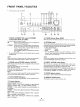
Connecting the speaker cords set to side A and one set to side B.
Cutter []
[] ,_ Speaker cord
10 mm Twist the strands.
17 Push up. Push d
2j Insert.
4
<.ARB1470>