DUCTLESS MINI SPLIT SYSTEM AIR CONDITIONER / HEAT PUMP WYT Inverter Series For 9,000-36,000 BTU/hr Systems Installation & User’s Manual CS78421-548-754 IMPORTANT NOTICE: Please read this manual carefully before installing or operating your new air conditioning system. Be sure to save this manual for future reference.
Table of Contents Installation Manual 0 Safety Precautions........................... 4 1 System Components........................ 6 2 Included Accessories...................... 7 3 Indoor Unit Overview..................... 8 4 Operating Instructions......... 9 1. Remote Buttons Overview.............................. 9 2. Remote Controller LED Screen And Icons.... 10 3. Handling the Remote Controller................... 11 4. Controlling the System’s Airflow.................... 12 5.
7 Outdoor Unit Installation.............. 30 1. Outdoor Unit Installation Location Selection............... 30 2. Mounting Instructions.................................................... 31 3. Electrical Wiring of the Outdoor Unit............................ 32 4. Connection of Refrigerant Piping.................................. 34 5. Evacuating the Lineset.................................................... 37 MC MC 8 Leak Check/Test Run....... 39 1. Electrical and Gas Leak Check.............
Safety Precautions Read and Understand All Safety Precautions Prior to Installation Improper installation due to negligence of instructions may result in serious damage or injury. The magnitude of potential damages or injuries is classified as either a WARNING or a CAUTION. This symbol indicates that ignoring the related instructions may cause death, or serious injury.
WARNING 6. For all electrical work, follow all local and national wiring standards, regulations, and especially this Installation Manual. You must use an independent circuit and a dedicated breaker to supply power. Do not connect other appliances to the same circuit. Insufficient electrical capacity or defects in electrical work can cause electrical shock or fire. 7. For all electrical work, use the specified cables.
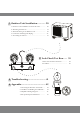
1 System Components High Wall-Mounted Air Conditioner The system is made up of two or more units connected together via insulated copper pipes and an electrical communication cable. The indoor unit is mounted onto one of the walls in the room that is to be conditioned. The outdoor unit is installed on the ground outside or on the wall of the dwelling using suitable mounting brackets. INDOOR UNIT 1 2 3 No.
2 Included Accessories Accessories and Components: The air conditioning system comes with the following accessories. Use all of the installation parts and accessories to install the air conditioner. Improper installation may cause the equipment to fail, or result in water leakage, electrical shock, or fire.
Owner’s Manual 3 Indoor Unit Overview Front Panel Display 2 1 3 4 5 4 3 2 Description No. LED Icon Symbol 1 POWER Indicates that the unit is currently powered on 2 SLEEP Indicates that the system is currently in SLEEP mode 3 Temp.
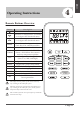
4 Remote Buttons Overview Button Description Turns the air conditioner on or off Decreases set temperature, set timing, or navigates the functional menu Increases set temperature, set timing, or navigates the functional menu MODE Selects the mode of operation (Auto, Cool, Dry, Fan, and Heat modes) Activates/deactivates the ECO feature Activates/deactivates the TURBO feature, which allows the system to TURBO reach set temperatures quicker ECO FAN Configures the fan speed (Auto, Low, Mid, and High) TI
Owner’s Manual 4 Operating Instructions Remote Controller LED Screen and Icons 4 5 6 7 8 3 9 10 2 11 1 12 18 17 16 15 14 13 Description Description No. 1 Fan Speed 10 Battery 2 Temperature 11 Turbo Mode 3 Auto Mode 12 Mute Function 4 Cooling Mode 13 I Feel/Follow Me Mode 5 Dry Mode 14 6 Fan Only Mode 15 46°F Freeze Protection Up-Down Auto Swing 7 Heating Mode 16 Left-Right Auto Swing 8 ECO Mode 17 Health Function 9 Timer 18 Sleep Function No.
Replacement of Batteries Remove the battery cover from the rear of the remote controller, by sliding it downward in the direction of the arrow as depicted below. Install batteries according to the depicted directions (+ and -) as shown on the remote controller. The cover then slides back into place. Use 2x AAA batteries. Do not use re-chargeable batteries. Replace old batteries with new ones of the same type when the display is no longer legible. Do not dispose of batteries as unsorted municipal waste.
Owner’s Manual 4 Operating Instructions Regarding the Airflow of the Indoor Unit Filter The air that is pulled in by the fan (the “return air”) enters the grille and is passed through the filter. It is then cooled/dehumidified/heated through the heat exchanger. Heat The direction of the air output is manipulated up and down by the motorized louver, and left to right via manually controlled vertical deflectors.
4 COOLING Mode Cooling mode allows the air conditioner to cool the room while also reducing the humidity of the air in the room. To put the system into cooling mode, press the button until the symbol appears on the remote’s display. The and buttons can then be used to set a temperature lower than that of the room. HEATING Mode Heating mode allows the air conditioner to heat the room. To put the system into heating mode, press the button until the symbol appears on the remote’s display.
Owner’s Manual Operating Instructions DRY Mode Dry mode is a limited function that can help reduce the humidity/moisture of the room. To put the system into dry mode, press the button until the symbol appears on the remote’s display. An automatic preset of this mode is then activated. FAN-ONLY Mode Fan-only mode is used to set the system to use only air ventilation and no heating or cooling. To put the system into fan-only mode, press the button until the symbol appears on the remote’s display.
4 Turning the Display On or Off The LED display on the front panel of the system can be turned on or off as desired. To do so, press the button in order to switch off the LED display on the front panel. This button can be pressed again to turn the LED display back on. SLEEP Mode Sleep mode is generally meant for periods of lower cooling requirements, such as during typical sleeping hours. This mode will result in decreased energy use, and can only be activated via remote control.
Owner’s Manual Operating Instructions Energy Saver (ECO) Option In this mode, the appliance will automatically manage the operation in order to save energy. To turn the ECO feature on, press the button on the remote, and the icon will appear. The system is now running in ECO, and the process can be repeated to turn it off. NOTE The ECO feature is available in both COOLING and HEATING modes.
4 Using the Timer - TIMER ON The TIMER feature allows you to set a time delay for the system to turn itself on or off. To set a time delay for the system to turn itself on in X number of hours: 1. Begin by pressing the button while the system is powered off. The symbol will then display. You can then set the needed modes. 2. Set the desired mode (COOL, HEAT, AUTO, FAN, DRY) by pressing the button. 3. Set the desired fan speed with the button. 4.
Owner’s Manual Operating Instructions 46°F Freeze Protection Function This feature is meant to be used to prevent freezing while the user is away from home. When turned on, it sets the system to keep a temperature of 46°F. If the unit is in standby, then the setting will automatically start the heating mode when the room temperature is equal to or lower than 46°F. It will set the system back to standby when the room temperature reaches 48°F.
4 I FEEL - To Ensure Comfort The I FEEL feature enables the remote to act as the temperature sensor and relay the current air temperature of where the remote is physically placed within the room. In some cases, this can aid with reducing thermal drift between the set temperature and the actual room temperature. In order to activate this feature, press the button, and the icon will appear on the display. Note: The I FEEL feature will automatically de-activate itself 2 hours later.
Owner’s Manual 4 Operating Instructions An Important Note Regarding Operating Temperatures The system is designed to run within a certain range of temperatures, which are listed below. There are built-in protections with the system that may stop the appliance when the ambient temperature goes outside of these ranges.
Maintenance of the Air Conditioner Periodic Maintenance Is Essential for The System! Maintaining the air conditioner will ensure that is stays efficient. Before carrying out any sort of maintenance, always ensure that the power supply to the system is turned off. Indoor Unit Anti-Dust Filters (Clean once every 2 weeks) 1. Open the front panel by pulling outward and upward at the indicated location. 2. Keep the front panel raised with one hand and take out the air filters with the other. 3.
Indoor Unit Installation Instructions 6 Indoor Unit Installation Location Selection Indoor Unit Installation Follow the below best practices for selecting an optimal space for installation the indoor unit: • DO NOT install the unit on a wall that is subject to vibrations. • DO NOT install the system near sources of heat, steam, or flammable gases. • DO NOT install the indoor unit in a location that is exposed to direct sunlight. • DO ensure that the inlet and outlet vents are not obstructed.
Indoor Unit Installation Instructions 6 Indoor Unit Installation Installation Diagram Before proceeding, it is important to consider the following height and length restrictions: Outdoor Unit Indoor Unit Pipe length is 50' max Height differential must be less than 16 ft. Height differential must be less than 16 ft. Indoor Unit Pipe length is 50' max Outdoor Unit Before starting the installation, decide on the position of both the indoor and outdoor units.
Indoor Unit Installation Instructions 6 Indoor Unit Installation Installation of the Mounting Plate 1. Place the included mounting plate against the wall where the system will hang that fulfills the constraints on Page 22. Use a level to ensure that the plate is horizontally level. 2. Drill 1.3” deep holes for each screw to enter, the locations are flexible but should be spaced well. ) 3.5mm ø 2.5” (6 3. Insert the plastic anchors into each of the holes. 4.
6 Indoor Unit Installation Instructions Electrical Connections - Indoor Unit All systems will include a wiring diagram affixed to the indoor unit. See Page 44 for more details. Wiring Diagram 2. Remove the cover as indicated in the illustration. 3. For the electrical wiring, consult the circuit diagram affixed to the electrical cover. 4. Connect the cables to the wiring terminal by following the numbering. Use wire gauge suitable for the electrical power input. (see name plate on the unit).
Indoor Unit Installation Instructions 6 Indoor Unit Installation Preparing the Refrigerant Piping of the Indoor Unit The piping “pigtails” pre-attached to the indoor unit can be run in 3 different ways as shown in the illustration. Decide which type of configuration is most suitable before continuing. By default, it is routed for a left side exit as shown in #1. This method can either use the left side knockout for a side exit, or a wall hole can be drilled on the left side of the unit’s rear.
6 Indoor Unit Installation Instructions Connecting the Drain Hose Indoor Unit Installation By default, the drain hose is attached to the left-hand side of unit (“left” when facing the back of the unit). However, it can also be attached to the right-hand side. 1. To ensure proper drainage, attach the drain hose on the same side that your refrigerant piping exits the unit. 2. Attach any drain hose extensions (sold separately) to the end of drain hose. 3.
Indoor Unit Installation Instructions 6 Indoor Unit Installation Connecting the Signal Cable Color selection does not matter as much as matching number to number does. Consult the diagram affixed to the indoor and outdoor unit respectively for specific wiring instructions. There are 3 terminals (1, 2, 3) and ground (G). Do not mix up the wires between each end. It is vital that the colors between the indoor and outdoor unit match for each terminal.
6 Indoor Unit Installation Instructions Connecting the Refrigerant Piping to the Indoor Unit Indoor Unit Installation Once the copper piping kit coil is unwound, refer to the below instructions to proceed: 1. Bring the ends of both the copper line and the indoor unit line together. Align the centers of the pipes that will be connected. 2. Remove the indoor unit piping cap, and check that no debris is inside. Some gas may be heard escaping, it is just nitrogen. 3.
Outdoor Unit Installation Instructions 7 Outdoor Unit Installation Location Selection Follow the below best practices for selecting an optimal space for installation the indoor unit: • DO NOT install the unit near sources of heat, steam, or flammable gases. • DO NOT install the system in areas prone to extreme winds or dust. Outdoor Unit Installation • DO NOT install the outdoor unit in an area that has many passersby.
7 Outdoor Unit Installation Instructions Outdoor Unit Installation Mounting the Outdoor Unit to the Selected Location The outdoor unit should be installed either on a pad or on a solid wall and fastened securely. Follow the procedure below before connecting any pipes or cables: • Decide what the best position on the wall or on the ground is, and leave enough space to be able to carry out maintenance easily. Anchoring dimensions are provided on Page 42.
Outdoor Unit Installation Instructions BEFORE PERFORMING ANY ELECTRICAL WORK, READ THESE REGULATIONS 1. All wiring must comply with local and national electrical codes, and must be installed by a fully licensed electrician. Outdoor Unit Installation 2. All electrical connections must be made according to the Electrical Connection Diagram located on the side panels of the indoor and outdoor units. 3. If there is a serious safety issue with the power supply, stop work immediately.
7 Outdoor Unit Installation Instructions Power/Signal Electrical Wiring to the Outdoor Unit On the outdoor unit, the wiring diagram is located in the inner side of the handle cover. The outside unit’s terminal block is protected by an electrical wiring cover on the side of the unit. A comprehensive wiring diagram is printed on the inside of the wiring cover. Cover Outdoor Unit Installation 1. Unscrew and remove the handle on the right side plate of the outdoor unit. 2.
7 Outdoor Unit Installation Instructions Connection of the Refrigerant Piping The length of refrigerant piping will affect the performance and energy efficiency of the unit. Nominal efficiency is tested on units with a pipe length of 5 meters (16 ft). Refer to the table below for specifications on the maximum length and drop height of piping. Pioneer WYT Series Mini Split MODEL/Capacity (Btu/h) 9K 1/4” Liquid Pipe Diameter 1/4” 18K 24K 36K 1/4” 1/4” ( 6.35) 1/4” ( 6.35) ( 6.35) ( 6.35) ( 6.
7 Outdoor Unit Installation Instructions Step 3: Flare pipe ends Proper flaring is essential to achieve an airtight seal. 1. After removing burrs from cut pipe, seal the ends with PVC tape to prevent foreign materials from entering the pipe. 2. Sheath the pipe with insulating material. Outer Diameter of Pipe (mm) A (mm) Min. Max. Ø 6.35 (Ø 1/4”) 0.7 (0.03”) 1.3 (0.05”) Ø 9.52 ( Ø 3/8”) 1.0 (0.04”) 1.6 (0.06”) Ø 12.7 (Ø 1/2”) 1.0 (0.04”) 1.8 (0.07”) Ø 16 (Ø 5/8”) 2.0 (0.08”) 2.2 (0.
7 Outdoor Unit Installation Instructions Instructions for Connecting Piping to Outdoor Unit Outdoor Unit Installation 1. Unscrew the cover from the packed valve on the side of the outdoor unit. MINIMUM BEND RADIUS When bending connective refrigerant piping, the minimum bending radius is 10 cm (4”). Valve Cover Radius ≥10cm (4 in) 2. Remove protective caps from the valve ends. 3. Align flared pipe end with each valve, and tighten the flare nut as tightly as possible by hand. 4.
7 Outdoor Unit Installation Instructions Air Evacuation and Bleeding the Circuit The air and/or humidity left inside the refrigeration circuit can contaminate the refrigerant and cause abnormal spikes in pressure, leading to eventual compressor malfunction. Therefore, after having connected the indoor and outdoor units to create a closed system, it is necessary to bleed the air and humidity out of the circuit by using a vacuum pump.
7 Outdoor Unit Installation Instructions Evacuation Instructions (Continued) 6. Turn on the vacuum pump to evacuate the system. 7. Run the vacuum for at least 15 minutes, or until the Compound Meter reads -76cmHG (-100 kPa or -30 inHg). Flare Nut Outdoor Unit Installation 8. Close the low-pressure side of the manifold gauge, and turn off the vacuum pump. 9. Wait for 5 minutes, then verify that there has been no rise in the vacuum reading. Cap 10.
Electrical/Gas Leak Check and Test Run ELECTRICAL SAFETY CHECKS BEFORE TEST RUN Check Grounding Work Measure grounding resistance by visual detection or with a grounding resistance tester. Grounding resistance must be less than 4Ω. Note: This may not be required in some locations. DURING TEST RUN Check for Electrical Leakage During the Test Run, use an electroprobe and and multi-meter to perform a comprehensive electrical leakage test.
Electrical/Gas Leak Check and Test Run 8 Test Run BEFORE TEST RUN TEST RUN INSTRUCTIONS Only perform a test run after the following steps have been completed: The following test run should be performed for 30 minutes: Electrical Safety Checks Confirm that the unit’s electrical system is safe and is operating properly. Gas Leak Checks Check all flare nut connections and confirm that the system is not leaking.
9 Troubleshooting MALFUNCTION POSSIBLE CAUSES If there’s running water... If a fine mist is coming from the air outlet...
A Appendix Anchoring the Outdoor Unit The outdoor unit can be anchored to the ground or to wall-mounted brackets. The following is a list of different outdoor unit sizes and the distance between their mounting feet. Prepare the installation base of the unit according to the dimensions found below: Outdoor Unit Installation Pioneer WYT Series Mini Split MODEL/Capacity (Btu/h) A B D H W1 W2 WYT009ALFI19RL (9,000 BTU - 110/120V) 438 mm 17-1/4 in. 278 mm 10-15/16 in. 284 mm 11-3/16 in.
A Appendix Guidelines for Drilling the Wall Hole Below are the suggested locations for the wall hole for systems between 9,000 - 36,000 BTU. Both left side/right side exits are considered. Confirm holes are appropriate by corner tracing.
A Appendix Guidelines for Drilling the Wall Hole (continued) 231/8” 83/8” 121/4” 133/8” 21/2” 65/8” Ø21/2” Ø21/2” 13/4” 13/4” 5/8” 17/8” Left Side Exit 13/4” 461/2” (For 24K-36K Systems) All Distances in Inches Appendix Simplified Wiring Diagram (115V and 230V) Page 44 Right Side Exit
Appendix A European Disposal Guidelines This appliance contains refrigerant and other potentially hazardous materials. When disposing of this appliance, the law requires special collection and treatment. Do not dispose of this product as household waste or unsorted municipal waste. When disposing of this appliance, you have the following options: • Dispose of the appliance at a designated municipal electronic waste collection facility.
The design and specifications of this product are subject to change without prior notice as development continues. Consult with the sales agency or manufacturer for details. Refer to the equipment nameplate for all other applicable specifications. is a registered trademark of Parker Davis HVAC International, Inc. Parker Davis HVAC International, Inc. 3250 NW 107 Avenue, Doral, FL 33172 - USA Tel : (305) 513-4488 Fax : (305) 513-4499 E-mail : info@pd-hvac.com Website : www.pd-hvac.